Automatic Plant Watering System
A smart IoT gardening assistant that monitors soil and air conditions to automate watering.
Author: Andrei Anghelea
GitHub Project Link: https://github.com/UPB-PMRust-Students/project-dm-2025-AngAndrei
Description
The Automatic Plant Watering System is an embedded IoT solution designed to maintain optimal conditions for indoor plants. Built around an STM32 microcontroller, the system intelligently monitors both soil moisture and ambient temperature/humidity to make watering decisions.
The system is designed for flexibility, offering two modes of operation:
- Automatic Mode: The system autonomously activates the water pump when soil moisture drops below a critical threshold.
- IoT Remote Mode: Using an ESP8266 Wi-Fi module, the device connects to a mobile app/web dashboard, allowing the user to view real-time environmental data and trigger the watering pump remotely.
Motivation
I chose this project to address a recurrent, common daily problem for me and my family and friends: keeping house plants alive during busy periods or vacations. Plants often die due to irregular watering, sometimes because owners forget.
From an engineering perspective, this project demonstrates:
- Hybrid Power Management: Using a dedicated Breadboard Power Supply to drive high-current actuators (pumps) while keeping the microcontroller logic safe.
- IoT Bridge Implementation: Creating a UART-to-Wi-Fi bridge between an ARM Cortex-M4 (STM32) and an ESP8266.
- Multi-Sensor Fusion: Combining analog data (soil) and digital protocol data (DHT11) in a real-time Rust application.
Architecture
Component List
- STM32 (Controller): Orchestrates the logic, reads sensors, and sends commands.
- Sensors:
- Soil Sensor: Analog reading of soil water content.
- DHT11: Digital reading of air temperature and humidity.
- Actuator: A 5V Submersible Pump controlled by a MOSFET (Low-Side Switch).
- Connectivity: ESP8266 communicating via UART (TX/RX) to send JSON data to the cloud.
Log
Weeks 3 - 9 and 10 - 16 November
- Project Selection: Researched various embedded project ideas and selected the "Automatic Plant Watering System" due to its practical utility.
- Requirements Definition: Decided on the core architecture: using an STM32 for control and an ESP8266 for Wi-Fi connectivity.
- Planning: Created the initial project outline and defined the necessary features (Automatic Mode vs. Remote App Control).
Weeks 24 November - 7 December
- Component Selection: Finalized the Bill of Materials (BOM), ensuring compatibility between the 3.3V logic of the STM32 and the 5V requirement of the pump.
- Procurement: Ordered the specialized components (Soil Sensor, Submersible Pump, Breadboard Power Supply).
- Inventory: Verified existing components from Arduino starter kits (DHT11, Resistors, Wires) to ensure nothing was missing.
- Arrival: Received the ordered parts and performed a visual inspection.
Weeks 8 - 14 December
- Hardware Testing: Individually tested the new components:
- Verified the Breadboard Power Supply output (5V/3.3V rails).
- Tested the Submersible Pump functionality directly on power.
- Calibrated the Soil Moisture Sensor (Dry air vs. Water readings).
- Integration Tests: Experimented with the MOSFET circuit to switch the pump on/off using a simple signal.
- Final Sourcing: The last remaining components arrived, completing the hardware set.
Week 15 - 21 December
- Documentation: Started writing the comprehensive project documentation (Architecture, Hardware, Software sections) on the website.
- Core Logic: Began developing the main software logic in Rust, defining the application structure.
- State Machine: Designed the primary state machine (Sleep -> Measure -> Decide -> Report) to serve as the base for the code implementation.
Week 12 - 18 January
- Component Integration: Connected the Soil Moisture Sensor and DHT11 to the STM32 Nucleo board on the breadboard.
- Initial Code Testing: Wrote and flashed the initial Rust driver code to verify accurate readings from both sensors via the defmt logger.
- Actuator Prep: Soldered male jumper headers onto the Submersible Pump wires to allow for a secure connection to the breadboard.
- Bridge Configuration: Flashed the ESP-01 with the custom "Wi-Fi Manager" firmware to handle ThingSpeak communication.
Week 19 - 25 January
- Circuit Completion: Built the MOSFET Low-Side Switch circuit (Transistor + Flyback Diode) to safely interface the 5V Pump with the 3.3V STM32 logic.
- Power Rail Setup: Configured the MB102 Power Supply to provide separate 5V (for the pump) and 3.3V (for the STM32/ESP) rails.
- Final Polish: Tided up the wiring and finalized the documentation photos.
Hardware
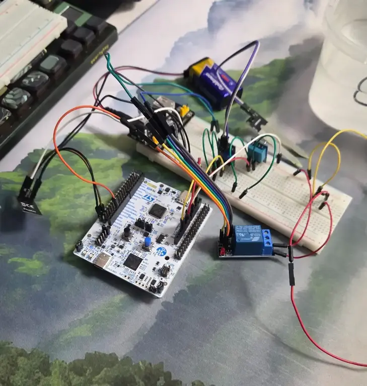
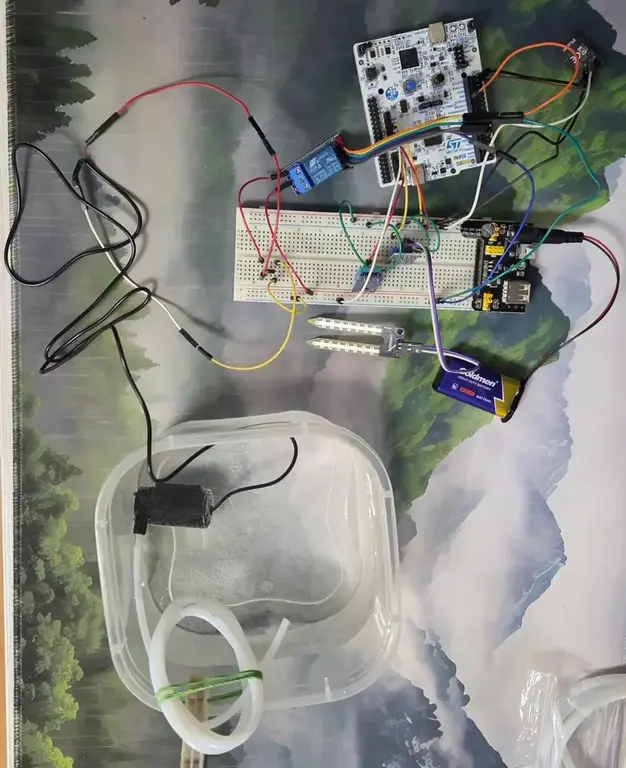
Schematics

Bill of Materials
| Device | Usage | Price(Ron) |
|---|---|---|
| STM32 Board (Nucleo-U545RE-Q) | Main Controller | 128 |
| Breadboard Power Supply (MB102) | Provides stable 5V & 3.3V rails | 4.69 |
| 9V Battery + Jack Clip (or 12V Adapter) | Input power for the Breadboard Supply | 1.5 |
| ESP8266 (ESP-01S) | Wi-Fi Connectivity (UART) | 17.49 |
| Mini Submersible Pump (5V) | Watering Actuator | 10 |
| Soil Sensor v1.2 | Analog Moisture Sensor | 4 |
| DHT11 Sensor | Air Temp & Humidity | 10 |
| IRLZ44N MOSFET | Switch for the Pump | 5 |
| 1N4007 Diode | Flyback Protection (for Pump) | 0.5 |
| Resistors (10kΩ, 1kΩ) | Resistors | 1 |
| Jumper Wires & Breadboard | Connections | 10 |
| Vinyl Tubing (6mm) | Water transport | 10 |
Software
| Library | Description | Usage |
|---|---|---|
embassy-stm32 | Hardware Abstraction Layer (HAL) | Controls the ADC (Soil Sensor), GPIO (Pump), and UART (ESP8266). |
embassy-time | Async Timer | Manages non-blocking delays (e.g., watering for exactly 5 seconds). |
dht-sensor | DHT11 Driver | Specialized driver to read Air Temperature & Humidity from the DHT11 sensor. |
heapless | Static Data Structures | Used to create fixed-size String buffers for formatting the UART messages ("22,50,4000\n"). |
panic-probe | Panic Handler | Handles system panics by printing the error location to the debug console. |
Detailed Software Functionality
The system architecture is divided into:
System Initialization & Configuration
Clock & Peripherals: Configuring the STM32 system clocks and enabling power to necessary GPIO ports. ADC Setup: Initializing the Analog-to-Digital Converter (ADC1) with 12-bit resolution for precise soil moisture readings.
GPIO Configuration: Relay/Pump: Configured as Push-Pull Output, initialized to Low (OFF) to prevent accidental flooding during boot. DHT11: Configured as Open-Drain Output for single-wire bidirectional communication.
Communication (UART): Setting up USART1 (115200 baud) with Direct Memory Access (DMA) channels to send data to the ESP-01 without stalling the processor. Safety Delay: A mandatory 2-second stabilization pause at startup to settle power rails before any logic begins.
Modular Drivers Soil Sensor: Reads raw voltage values mapped to a 0–4095 range (where ~4000 represents dry air and less than 2000 represents water). DHT11 Protocol: Implements a custom "bit-banging" protocol that handles microsecond-level timing to handshake with the sensor and decode the 40-bit temperature/humidity data stream.
Main Application Loop
Sensor Acquisition Phase: Performs a blocking read of the Soil Moisture Sensor (PA0). Performs an asynchronous query of the DHT11 Sensor (PA4) to fetch Temperature (°C) and Humidity (%).
Telemetry Phase: Formats sensor data into a CSV string (TEMP,HUM,SOIL\n). Transmits the string via UART/DMA to the ESP-01 module for Wi-Fi upload (ThingSpeak).
Control Logic (The Decision Engine): Threshold Check: Compares the Soil Moisture value against the defined "Dry Threshold" (3000). Activation: If the soil is dry (>3000), the system asserts the Relay Pin (PA5) High. Timing Control: The pump runs for a strictly enforced 3-second window using Timer::after_secs(3). Deactivation: The Relay is forced Low immediately after the window closes.
Sleep Cycle: The system enters a low-power async wait state for 15 seconds before repeating the loop, allowing the soil water levels to settle.
Links
- The Embedded Rust Book - Core concepts for Rust on microcontrollers.
- Embassy Framework Documentation - The primary framework used for the async logic.
- ESP8266 AT Command Set - Reference for commanding the Wi-Fi module via UART.
- DHT11 Rust Driver (dht-sensor) - Documentation for the specific sensor library.