Digital Oscilloscope
A digital oscilloscope that displays the most important parameters
Author: Lazaroiu Mihai
GitHub Project Link: https://github.com/UPB-PMRust-Students/project-mihai1402
Description
This project’s main function is to demonstrate the functionality of a digital oscilloscope programmed in Rust. The hardware consists of:
- An analog pre-amplifier for preparing the input signal
- A microcontroller for signal processing
- A debugger to aid the microcontroller during testing
- A screen for display
The software allows the hardware to perform various functions of an oscilloscope like displaying an external signal and measuring its key parameters.
Motivation
I chose to build an oscilloscope,to combine my interest in electronics and audio signals with a practical and useful application. It also helps me understand theoretical concepts I've learned so far.
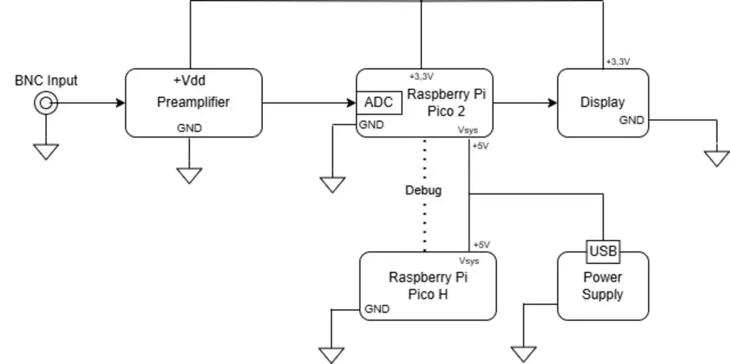
Architecture
The hardware is composed of four main components:
- Pre-amplifier
- Built using resistors, diodes, capacitors, and an op-amp in a non-inverting configuration.
- Processing unit
- Based on the Raspberry Pi Pico 2 (main processor) and Raspberry Pi Pico H (debugger during testing).
- Display
- Visualizes the signal from the microcontroller.
- Power supply
- Feeds all the components with necessary voltage.
These 4 components work together to form the oscilloscope in the following way:
Signal flow:
- Input signal → probe → pre-amplifier → ADC (Pico 2) → display.
Power setup:
- Raspberry powered via USB; peripherals via 3.3V GPIO pin.
Log
Week 12
- Moved my hardware from the breadboard to a protoboard
Week 11
- Decided on a screen to use for the final hardware iteration of the project
- Developed a working program that receives ADC data and displays it on the screen
Week 10
- Wrote the documentation
- Finished the pre-amplifier
- Tested different screen types by drawing signal functions
- Note: Final screen model still undecided, so specified crate is not yet final
Week 9
- Troubleshooting the pre-amplifier
- Started more detailed software design
Week 8
- Started building the pre-amplifier
Week 7
- Parts arrived
- Began planning next steps
Week 6
- Ordered parts for the pre-amplifier
Week 5
- Finished initial plan (hardware & software bill of materials)
- Uploaded project idea document
Week 4
- Brainstormed project ideas
Hardware
Components
- 5x Resistors (R1 → R5)
- 5x Capacitors (C1 → C5)
- 1x Diode (D1)
- 1x Op-amp (MCP6002, non-inverting configuration)
- Power source
- Raspberry Pi Pico 2
- Raspberry Pi Pico H
- Display: WaveShare Pico-ResTouch-LCD-2.8
- Probe
Function of Components
C1: used to eliminate the DC componentR1,R2: form a voltage divider that ensures the input biasR3,R4: are used to set the amplification factor of the op-amp to 1C2: used so that the amplification only applies to the AC componentOp-amp: part of a MCP6002 integrated circuit that has 2 operational amplifiers. Only one of the 2 was used. A secondary function of the amplifier in combination with the voltage that powers it is to limit the max amplification in order to protect the internal ADC of the microcontrollerC3: used to make sure no DC component enters the ADC, after the operational-amplifier.C1was used to block the DC component before the amplifierC4: used to block high frequencies from generating auto-oscillationsC5: is used to eliminate spikes from a switching power supplyR5: limits potential high currents from affecting the ADCD1: used to protect the non-inverting input of the amplifier from negative voltages- Probe: used to acquire the signal
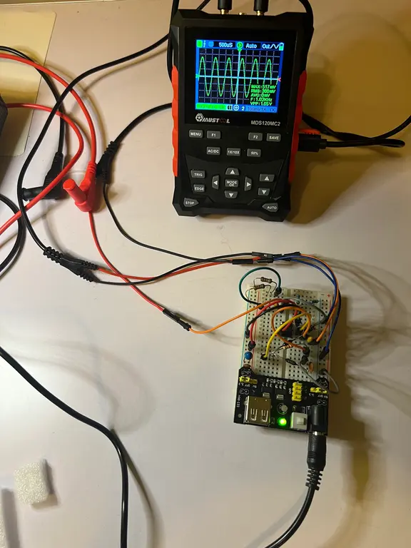
Prototype Photos
Breadboard analog pre-amplifier prototype:
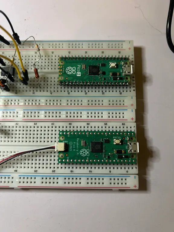
Processing hardware:
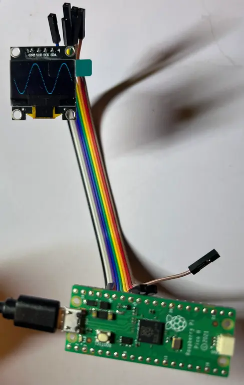
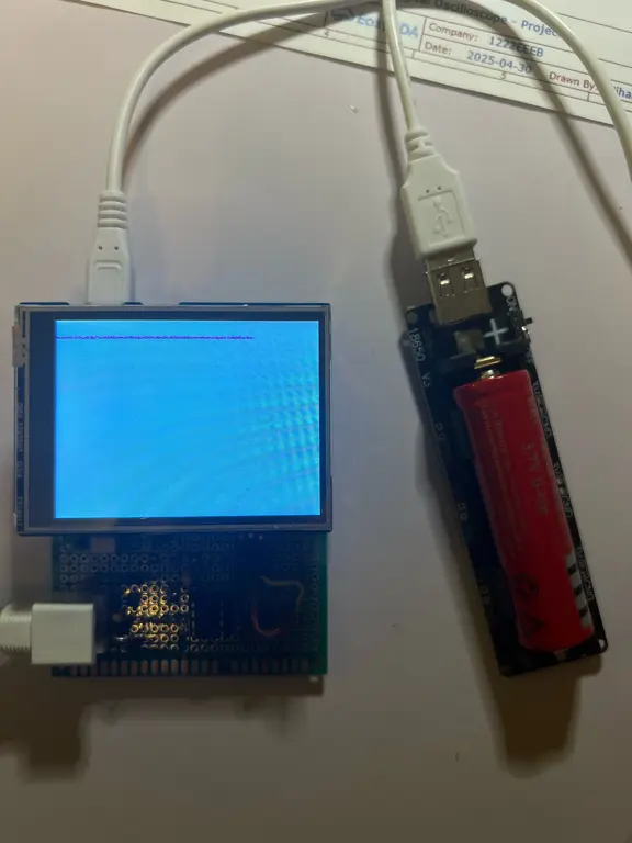
Signal on screen:
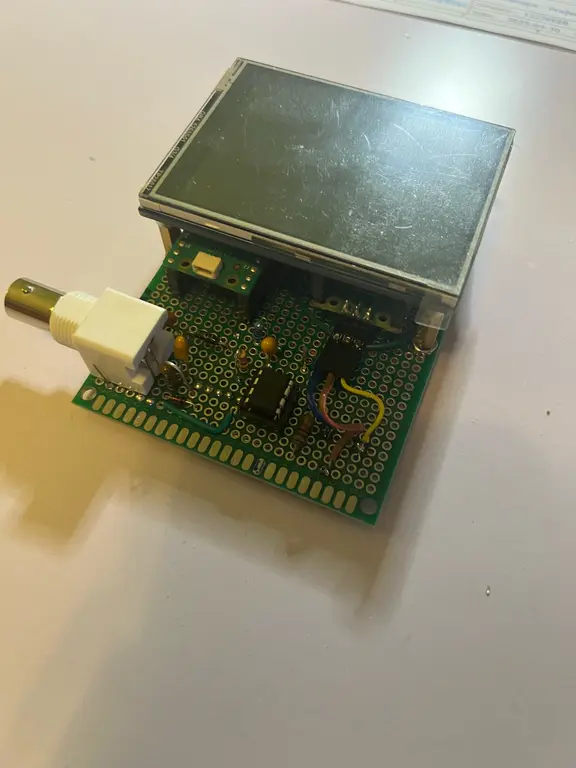
Final Hardware Photos
Digital Oscilloscope Unit:
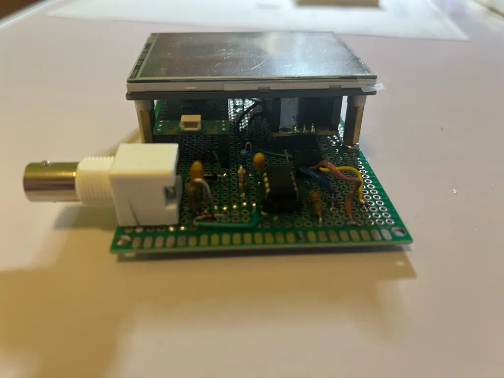
Side View:
Demo:
Schematics
The connections of the components described previously can be seen on the following electric diagram.

Bill of Materials
| Device | Usage | Price |
|---|---|---|
| BNC Female Connector | Connects the probe to the pre-amplifier | 5.83 RON |
| 1N4148 Diode | Protects the non-inverting input of the op-amp | 0.49 RON |
| 100kΩ Resistor (x2) | Voltage divider and amplification factor | 0.10 RON |
| 4µF Capacitor (x2) | DC decoupling | 0.49 RON |
| MCP6002-I/P Op-Amp | High input impedance operational amplifier | 3.00 RON |
| 1.8kΩ Resistor | Amplification factor setting | 0.05 RON |
| 10nF Capacitor | Avoid DC amplification | 0.10 RON |
| 200Ω Resistor | Input current limiting for ADC | 0.10 RON |
| Li-Ion 3.7V Battery 18650 (x2) | Powers the oscilloscope | 32.00 RON |
| 100nF Capacitor | Avoid auto-oscillation | 0.10 RON |
| 10µF Capacitor | Avoid voltage spikes | 0.49 RON |
| Oscilloscope Probe | Signal acquisition | 79.99 RON |
| Raspberry Pi Pico 2 | Microcontroller unit (MPU) | 39.66 RON |
| Raspberry Pi Pico H | Debugging | 42.74 RON |
| WaveShare Pico-ResTouch-LCD-2.8 | Shows signal and parameters | 86.11 RON |
| IC Socket | Socket for op-amp | 1.37 RON |
| Header Pins | Connects Raspberry Pico | 0.95 RON |
| Breadboard + Prototype Power Source | Prototyping circuit | 25.57 RON |
Software
| Library | Description | Usage |
|---|---|---|
| embassy-rp | Raspberry Pi Pico 2 hardware abstraction | Used for interacting with peripherals like ADC, SPI, I2C, timers, and GPIOs to acquire and display waveform data |
| embassy-executor | Async task executor for embedded projects | Manages concurrent tasks for waveform sampling, processing, and display update in real-time |
| embassy-time | Timekeeping and async timers | Used to generate accurate sampling intervals for the oscilloscope and trigger time-based actions |
| embassy-sync | Async-safe signals, mutexes, and channels | Coordinates data flow between ADC sampling, processing, and the display task to ensure smooth real-time updates |
| heapless | Fixed-size data structures for no_std | Implements double buffering for waveform data to ensure no data loss during updates to the display |
| embedded-graphics | 2D graphics and text rendering | Renders waveforms, signal properties like amplitude/frequency, and other graphical elements on the display |
| ssd1306 | Display driver for I2C OLED screens | Controls the OLED display to show real-time waveforms and signal information in the oscilloscope |
| display-interface-i2c | Adapter crate for I2C display interface | Connects the SSD1306 driver to the embedded-graphics library via I2C communication |
| microfft | Lightweight FFT crate for no_std | Performs Fast Fourier Transform (FFT) to calculate the frequency of the signal in real time |
| cortex-m | Low-level access to Cortex-M processor features | Supports interrupts and system functions for handling ADC, DMA, and display updates |
| cortex-m-rt | Runtime crate for Cortex-M | Initializes the board and manages interrupt-driven tasks, including DMA and signal sampling |
| defmt | Logging crate for embedded projects | Provides debug logging for signal data, task progress, and error tracking in the oscilloscope |
| panic-halt | Panic handler for embedded projects | Safely halts the CPU on panic, ensuring stable operation in embedded systems like the oscilloscope |