Piano Player & Learner
A digital piano designed to help users learn and play songs with on-screen note guidance.
Author: Sirbu-Boeti Eduard-Cristian
GitHub Project Link: https://github.com/UPB-PMRust-Students/project-dm-2025-Sirbu-Boeti-Eduard
Description
The project is a 7-note piano intended as a simple learning system to follow the notes of a song. The user can play individual notes or up to two notes simultaneously, allowing for basic chords and harmonies aimed towards beginners. For intermediate learners we will make use of a joystick to experiment with changing the pitch of a note.
- We will use an LCD display to:
- Guide the user to follow the displayed notes of a chosen song
- Indicate system states (e.g. playing, recording, name of the song to be played etc.)
- The interface is a 4x4 button matrix used for controlling the system:
- 1st row: Play more difficult pre-recorded songs
- 2nd row: Guided play-along mode for easier songs using the display
- 3rd row: Record and save user-played songs
- 4th row: Auxiliary actions (start recording, confirm, cancel, etc.)
Motivation
The main motiviation behind this project was me wanting to make use of the 4x4 button matrix component. Initially I wanted to make the tabletop game Battleship, but I wasn't satisfied with there being only 16 possible square grids due to the size of the button matrix.
After fiddling around with buttons on the breadboard I liked the feel of it and wanted to try doing something with buttons that will fit nicely in your hand. Due to the size of the breadboard I was thinking of maybe using it as a remote controller for something but I ended up going with a small 7-note piano.
This was due to the fact that, when I was younger, I used to have a Yamaha digital piano with a lot of similar features and also because I saw that in previous years there have been similar piano projects.
Architecture
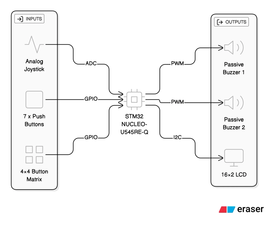
Inputs
- 7× Push Buttons
- Act as the main “piano keys” (Do, Re, Mi, Fa, Sol, La, Si)
- Connected as GPIO inputs with pull-ups
- 4×4 Button Matrix (Keypad)
- Used for system control (mode selection, song selection, confirm/cancel actions)
- Connected via GPIO row/column scanning
- Analog Joystick
- VRx and VRy connected to ADC inputs
- Used for experimenting with pitch control
- The joystick push button (SW) is not used/needed
Outputs
- 2× Passive Buzzers
- Controlled using PWM
- Support up to two simultaneous notes, naming the buzzers as "voices"
- 16×2 Character LCD (HD44780 controller chip)
- Displays current mode, target notes and system status
- Connected via I2C
Connections
- GPIO / EXTI – push buttons (note input)
- GPIO scan – 4×4 keypad (columns driven, rows read)
- ADC – joystick VRx / VRy
- PWM – passive buzzers (frequency = note pitch)
- I2C – LCD module
Log
Week 5: 27 October - 2 November
This was the week when we had to present our Powerpoint presentations. In this week, I just gathered the necessary information and created the presentation. There were no additional modifications requested by the professor, as such I took that the project received the "OK".
Week 6: 3 November - 9 November
This week I set up all 7 buttons on the breadboard and starting building a quick demo to see the overall difficulty. Initially I used a single buzzer, but I also wanted an additional one for concurrent notes. I didn't have an additional passive buzzer (only an active one) so I had to order one.
While waiting for the new buzzer, I managed to create the functional demo where i could play the notes through the buzzer.
Week 7: 10 November - 16 November
This week I wanted to connect the I2C display to the MCU. I initially had trouble with the identification of the I2C address, thus not being able to use the display and, as such, I had to wait to complete Lab 06 - "Inter-Intergrated Circuit" to finally be able to scan the correct I2C address and print "Hello World".
Around this time, I also received my second passive buzzer and I finally connected it and was able to play two notes at the same time.
Side note: I had to change all the button and the existing buzzer connections because I had to get the two buzzers to connect on different TIMs in order to play different notes at the same time.
Week 8: 17 November - 23 November
At this point, I had all the buttons and buzzers ready and the LCD display was just connected. Now, I wanted to connect the 4x4 button matrix. Here I struggled a lot because there were no markings on the on PCB of the order of the pins and their correspondence with the rows and columns. After finally thinking I got the connections right, I observed that it still wasn't working. I found out the the button matrix that I had simply wasn't detecting the entire rows 1 and 2 (I assume the pins that denoted the rows were broken because the columns had not problems). As such, I postponed this step in order to buy a new button matrix that hopefully works.
Side note: At this point, I deconnected for now the existing note buttons for testing as I no longer had space for the 8 pins of the button matrix and had no Female-to-Female connectors for connecting to the Morpho pins.
Week 9: 24 November - 30 November
This week I started testing my joystick to see if it is working properly. I decided that I didn't need to make use of the SW button (clicking the joystick) and that I will either use the X or Y axis for pitch control. After testing it worked properly the ADC and seeing the changes in terminal. At this point I wanted to try testing the pitch change on a static note, but the results were not satisfying, making it sound bad. Hoping to find a solution.
Week 10: 1 December - 7 December
This week I mostly did changes to the code in order to better segment the code for future implementation. Namely, preparing the "Free Play", "Play Along 1 (single notes)" and "Play Along 2 (double notes)" into different functions to be called in the "loop".
Week 11: 8 December - 14 December
After buying some Female-to-Female cable I was able to complete connection of all components together. I ended up not ordering a new button matrix, thinking that maybe it was my code's fault it wasn't working, but after several more tries I concluded that I need to buy a new button matrix. For now, until I buy the new one, I will have to work on the currently functional rows.
Week 12: 15 December - 21 December
This week I worked on writing the documentation and moving my segmented demos into a single Github repository for the source code. Starting to focus on the source code with all of its features.
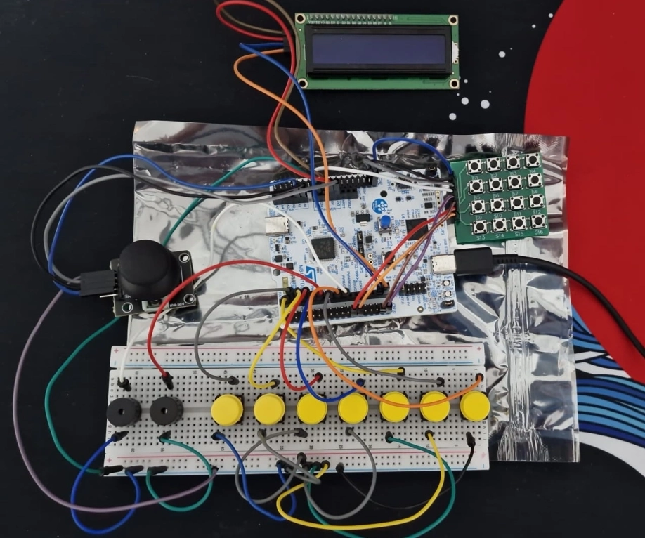
Hardware
I have provided links for reference.
-
Connecting components:
- Breadboard
- Male-to-Male, Male-to-Female, Female-to-Female Cables
Current pin usage
- LCD (I2C1)
- SCL:
PB6 - SDA:
PB7
- SCL:
- Buzzers (PWM)
- Buzzer 1:
PC9onTIM3_CH4 - Buzzer 2:
PB10onTIM2_CH3
- Buzzer 1:
- 7 Push Buttons
PC8,PB3,PB5,PB4,PA2,PC7,PC6
- 4×4 Button Matrix (Keypad)
- Columns 1->4:
PC13,PC12,PC11,PC10 - Rows 1->4:
PA9,PA10,PA11,PA12
- Columns 1->4:
- Joystick
- VRx / VRy on
A0,A1 - powered at 3.3 V
- Not using the SW(Joystick Click)
- VRx / VRy on
Schematics

Bill of Materials
| Device | Usage | Quantity | Unit Price | Subtotal |
|---|---|---|---|---|
| STM32 NUCLEO-U545RE-Q | Main microcontroller board; handles all input processing, sound generation and display control | 1 | ~100 RON | ~100.00 RON |
| Passive buzzer 3V | Audio output for generating musical notes via PWM | 2 | 0.99 RON | 1.98 RON |
| Yellow push button | Piano key inputs (Do–Si) | 7 | 1.99 RON | 13.93 RON |
| 4×4 Button Matrix Keypad | Menu navigation, mode selection and control input | 1 | 3.99 RON | 3.99 RON |
| LCD 16×2 with I2C interface | Displays current mode, notes and system feedback | 1 | 14.99 RON | 14.99 RON |
| Analog 2-axis joystick module | Experimental pitch / expression control via ADC | 1 | 5.35 RON | 5.35 RON |
| Breadboard | Prototyping platform for wiring components | 1 | — | — |
| Jumper wires (M-M, M-F, F-F) | Electrical connections between components | — | — | — |
Total hardware cost: ~140 RON
Software
| Library | Description | Usage |
|---|---|---|
| embassy-stm32 | Hardware Abstraction Layer (HAL) for STM32 in Embassy | GPIO (buttons + matrix scan), ADC (joystick), PWM timers (buzzers), I2C (LCD) |
| embassy-executor | Async task executor for embedded Rust | runs the async #[embassy_executor::main] entry point and the main event loop |
| embassy-time | Async timers and delays | scan timing for matrix, debounce-ish delays, periodic loop pacing (Timer::after_*) |
| defmt | Lightweight embedded logging framework | structured logs for button/keypad events, ADC debug, state transitions |
| defmt-rtt | RTT (Real-Time Transfer) transport for defmt logs | sends logs to the host while debugging (no UART required) |
| panic-probe | Panic handler for embedded targets | reports panics through the debug probe/RTT |
| embedded-hal | Traits for embedded drivers (portable interfaces) | used for I2C traits and PWM trait bounds |
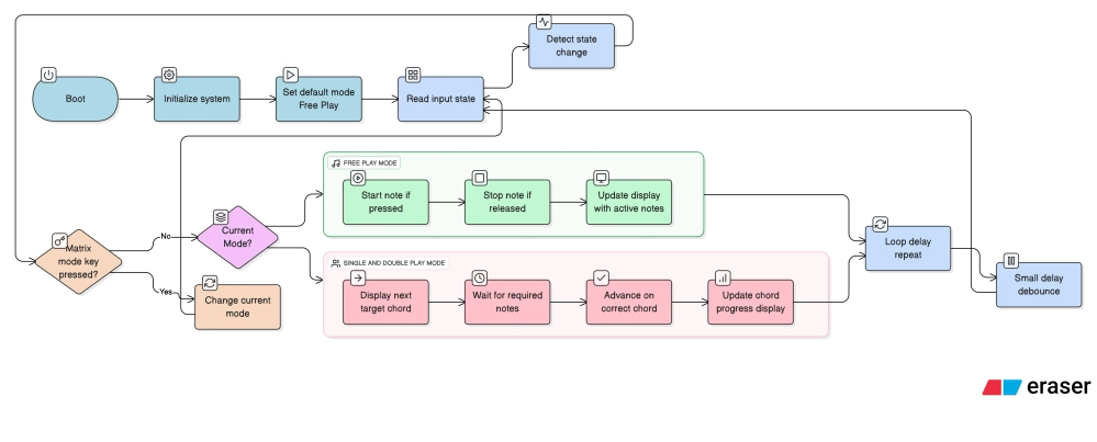
Detailed Software Design
The firmware is implemented as a single asynchronous control loop using the Embassy framework. All application logic is centralized in the main loop, with functionality divided into clearly defined stages.
The system is divided into:
- Initializing the components
- LCD: Finding the I2C address, passing the value to the constants
- Joystick: Calibrating the center of the joystick
- Buzzers: Creating the "voices" that will handle the notes
- Hardcoding the frequencies
- Attributing different functions for each of the buttons on the matrix
- Defining different modes (FreePlay, SinglePlay, DoublePlay)
- Main loop
- Default: FreePlay Mode
- Await button presses that trigger changes to a different mode
- Intermediary steps e.g. confirmation etc.
- Async functions
- These will be called when the main loop will switch control