Radu: Measuring the Speed of Light
Radu: Measuring the Speed of Light in a 6x1 setup.
Author: Sainenco Luchian (1221C)
GitHub Project Link: https://github.com/UPB-PMRust-Students/project-LucaSain
Description
In 1850s Fizeau measured the speed of light in a 8km setup using a gear. The key point of the measurement was that the light would travel the distance from the source and back slower than the aperture of the gear. Today, using high reflectivty mirrors, electrical motors and high precision laser cutting we can repeat Fizeau in a 3x1m setup.
Motivation
I went to ELI-NP Winter school and I enojyed the labs we had there so I decided to build my own "lab application" to measure the speed of light just like Fizeau did in 1850 but using modern technologies.
Architecture

Main Functionality
- 200mW 640nm Laser releases a beam
- The beam passes through the aperture of an aluminium disk
- The aluminium disk is rotating at about 7000rpm by an electrical engine (calibrated using PID)
- Next the beam reflects off a setup of high reflectivity mirrors
- Using a final mirror, the beam is reflected back the path and through the aperture
- A diode detects the intensity of the laser beam and is used to sample a signal
- By analysing the discrete signal the speed of light can be computed
We distinguish three main components:
- Control panel (interface)
- Motor & lasers control (PID)
- Sensors / detectors
More about these in the hardware part
Log
Week 5 - 11 May
- Tested the LLM capabiltiy and changed the project theme.
- Theoretical setup and architecture for the actual project.
Week 12 - 18 May
- Tested the disc with a VFD. Won the the first place at SCSS FILS ETTI with the experimental setup.
- Tried to build a AC driver circuit for the motors.
- Found a decent DC motor and driver.
- 3D design the case for the dashboard.
- Print the hardware to integrate the DC motor into the Grinder case.
- Ordered a new laser because the old one burned during the experimental setup.
- Designed holders for the high reflectivity mirrors.
- Add and complete the circuit schematics
Decided to settle on a simpler design on both dashboard and optics setup. See further.
Week 19 - 25 May
- Setup the Motor Control via PID
- Setup the Laser Optics
- Setup the Signal Capturing
- Inter board communication
- Finishing touches on the Dashboard
Hardware
The hardware will be built around esp32-based boards.
Control Panel Component
The first design of the control panel was reduced from the conceptual form.

This is the control panel for the whole setup.
- One 4 digit common anode display will be used to display the measured RPM for the motor.
- One potentiometer will be used to manipulate the speed of the motor.
- One potentiometer controls the brightness of the common anode display.
- One switch will arm and control the power status of the motor and laser.
- An emergency stop button will stop the motor and laser.
- The LCD display will show a plot of the signal captured through the diode.
- Everything driven by the ESP32-Wroom.

This is the Motor System, conceptual design.
- A high power H-bridge will drive the motor
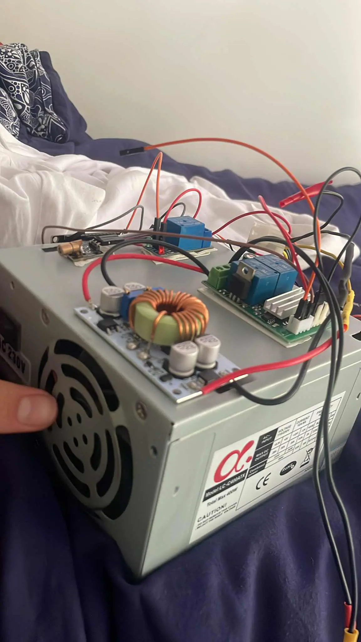
A power supply is needed (aluminium disk at 7000 rpm will eat some juice)A grinder can be powered directly by AC. A dimmer circuit is needed- I no longer have a VFD. The final decision was to use a motor driver with a high power dc motor. Everything powered by an ATX power supply.
- A small power laser and diode detector will be used to measure the real speed of the motor.
- A closed loop is thus created, making PID control possible.
- Two lasers, one high-power, one low-power, controlled via MOSFETS.
- Everything driven by the ESP32-Wroom.
Final pics of the motor-laser system.
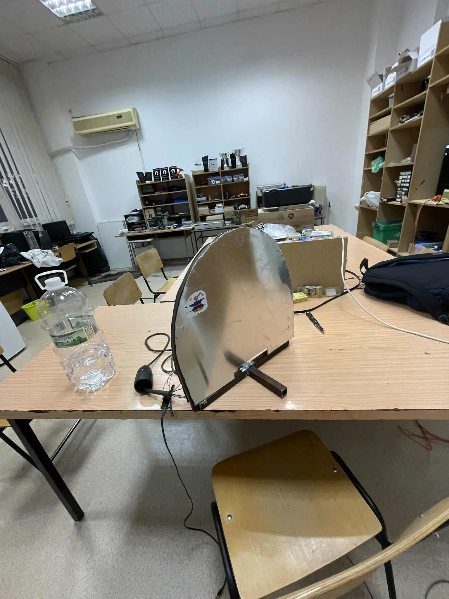

This is the Optics Control System concept. The calibration of the mirrors was done manually.
- A Class 3B (250mW) laser is used as a beam source (a class 3 B laser is dangerous. Wear protecting glasses when it's running).
- Stationary high reflectivity mirrors (about 98% reflected intensity) will reflect the ray back and forth
- Mobile high reflectivity mirrors will be used to focus the beam back into the aperture (calibration will be done manually).
- Diode detector will be used to focus the beam onto the detector diode.
- Everything driven by the ESP32-Wroom
Schematics
Control Panel Schematic

Optical Sensors

Final Motor Driver

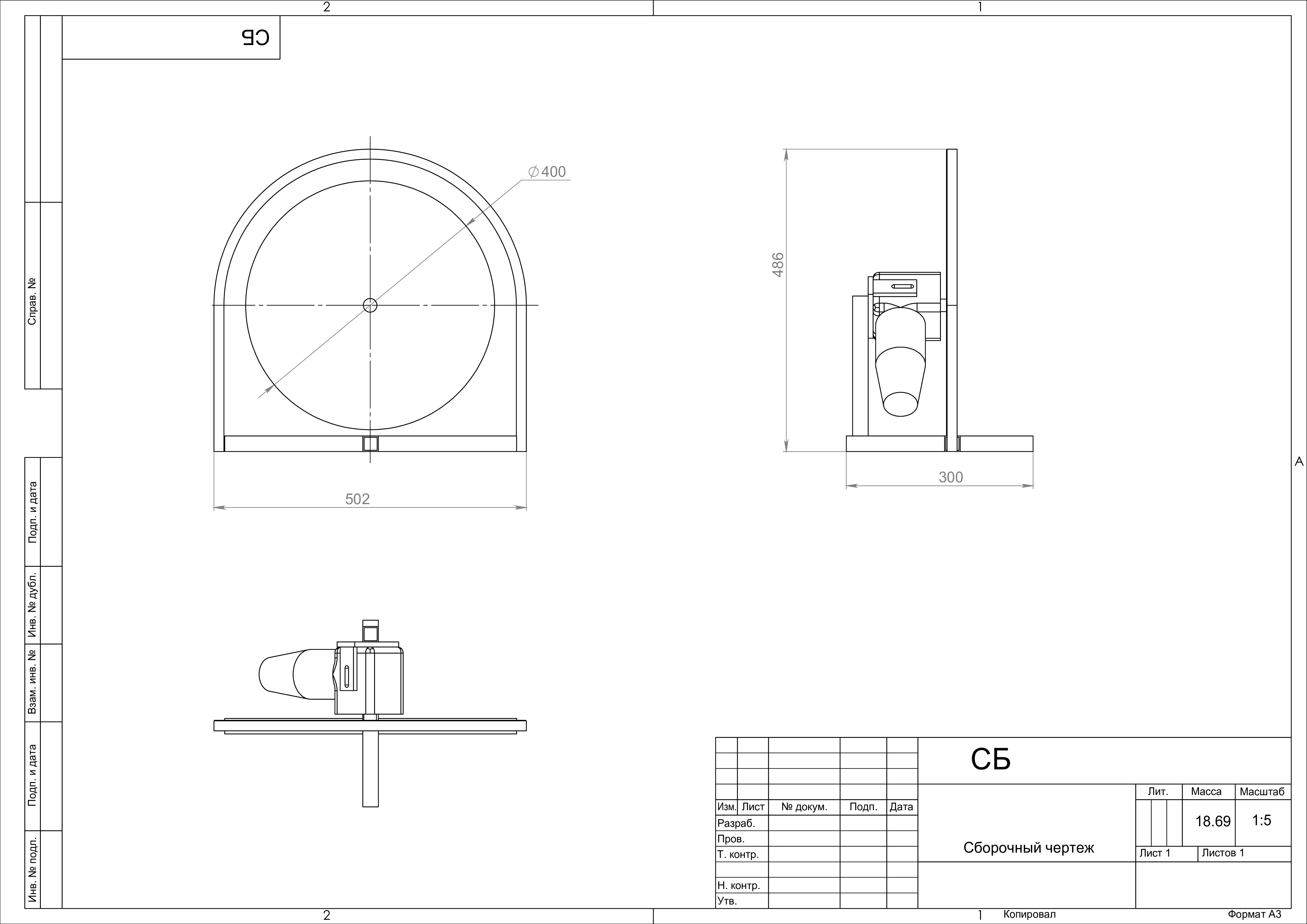
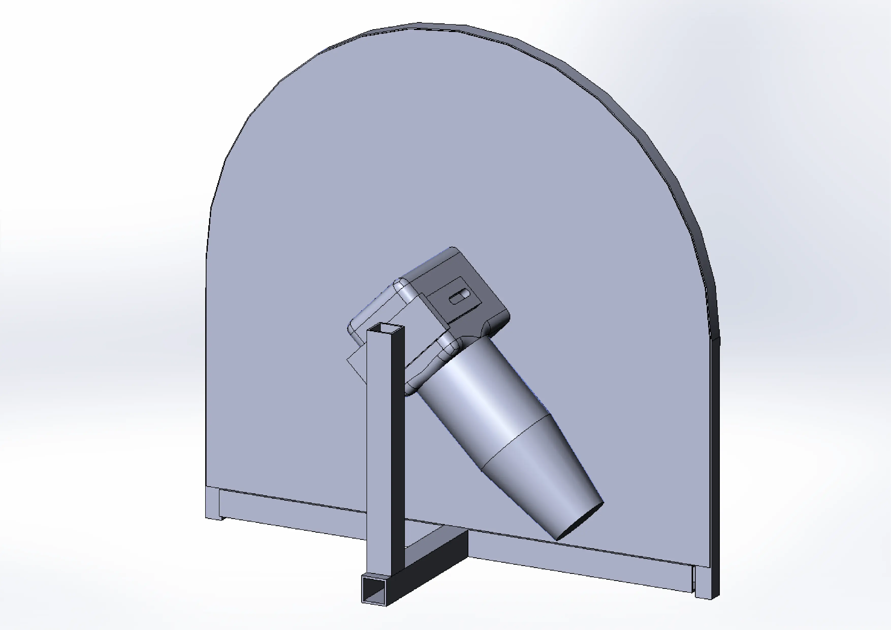
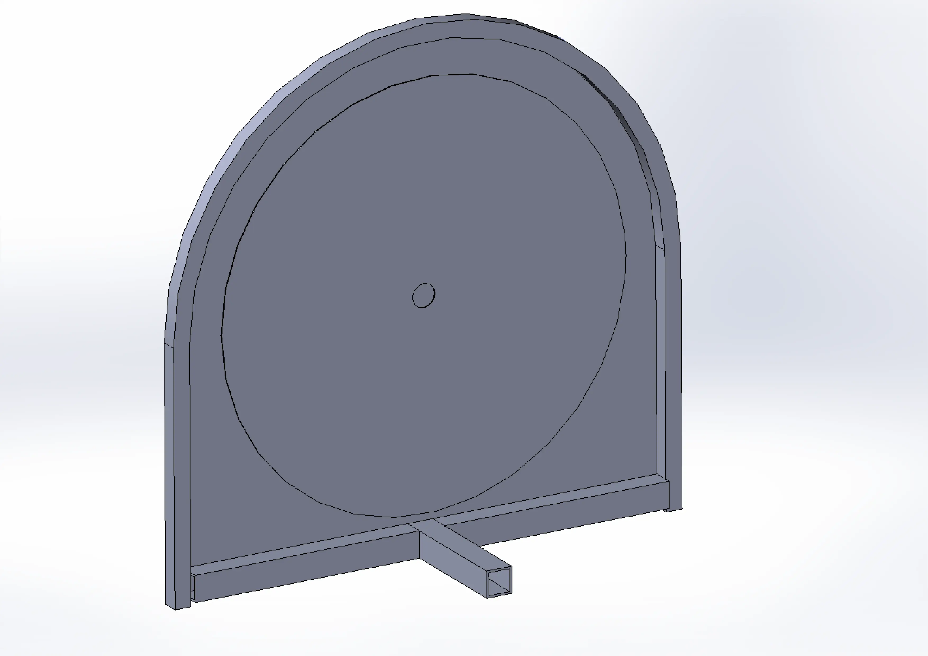
Disc, Case and Stand Schematics
Bill of Materials
| Device | Usage | Price |
|---|---|---|
| ESP32-WROOM (x2) | Controllers | 36RON |
| ESP32-S2 | Controllers | 13.07RON |
| High Reflectivity Mirrors | Mirros for increased optical path | 90.25RON |
| Class 3B laser x2 | Laser ray | 68RON |
| 4 Digit LED Common Anode (x1) | Display the measured and theoretical speed of the motor | 3.95RON |
| Push button with hold | Start/stop the laser/motor | 2.77RON |
| ON/OFF Switch | Arm/Disarm the laser/motor | 1.99RON |
| Relay module | Arm/Disarm the motor power supply | 7.99RON |
| SG90 Servo (x4) | Manipulate the calibration mirrors | 12RON |
| Potentiometers (x5) | Set the speed of motor/manipulate the mirrors calibration | 1.49RON |
| Red laser module | Motor Speed Measurement | 2.99RON |
| Photodiodes (x2) | Motor Speed Measurement and Sampling of the signal | ??? Searching for this |
| High Power H-Bridge | Motor Control | 99RON |
| DC 7000 rpm motor/(or Makita Grinder, if dimmer module available) | Rotation of the aluminium disk | lab/home donation |
| Aluminium disk | Rotation of apertures | Free, Recycled |
| ATX PSU | Motor and Lasers power | Free, Recycled |
| DC-DC Boost Convertor 250W | 12V (ATX PSU) to 24V conversion | 37RON |
Software
| sofware | purpose | documentation |
|---|---|---|
| esp-idf-hal/esp-hal | esp32 based-devices hal | documentation |
| pid | pid control for motor rpm | documentation |
| esp-wifi/esp-wifi-sys | wifi and esp-now bindings | documentation |
Links
Inspiration