Rusty Lock Access System
The Rusty Lock Access System is a multi-authentication security solution designed to control access using multiple user validation methods.
Author: Bejinaru Matei-Cristian
GitHub Project Link: https://github.com/UPB-PMRust-Students/project-Matty27100
Description
Built around the Raspberry Pi Pico 2W microcontroller, this project integrates an RFID reader, Wi-Fi-based control, a matrix keypad, LCD feedback display, and a servo motor attatched by an iron wire to a door latch. The goal is to provide secure, user-friendly access control that can be managed both locally and remotely.
Motivation
I've been brainstorming project ideas with a friend who shares my passion for technology and automation earlier this year. We came up with a few concepts for the Innovation Labs competition, with smart-home equipment being a central theme. Although we weren’t able to participate, the idea of creating a smart device stuck with me. When the time came to choose a project for this course, I knew I wanted to pursue something in that direction. That’s how I arrived at the idea of building a versatile smart lock system.
Architecture
Logical Diagram
The Diagram with all the components:
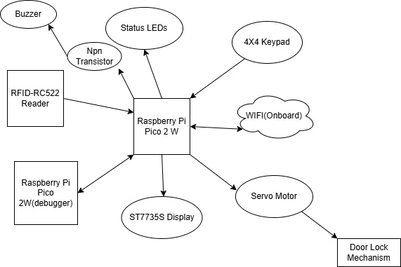
How it works
Initialization:
The system boots and initializes all components. The LCD displays a waiting message.
Authentication:
RFID: When a card is detected, its UID is checked against a known list.
Keypad: A valid PIN entered via the keypad is accepted.
Wi-Fi: Pressing the "Unlock" button on the web app sends a request that, if received, triggers the unlock.
Unlocking:
A validated user causes the servo to open the lock and display a message for a few seconds.
Locking:
After a delay, the servo returns to the locked position.
Log
Week 5 - 11 May
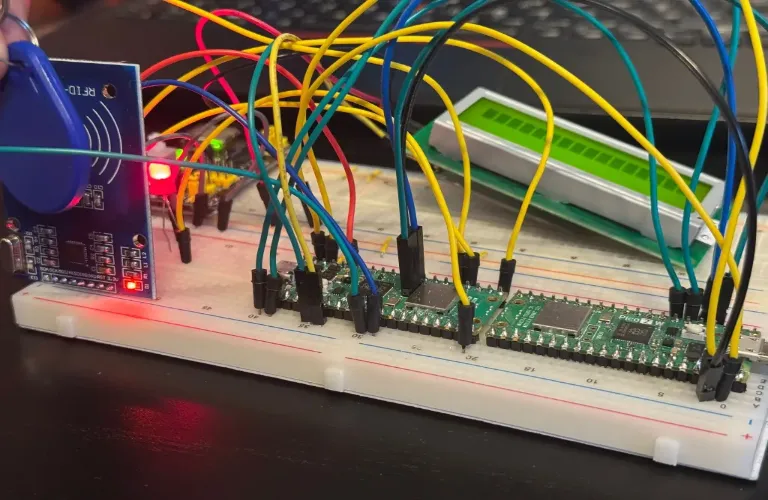
Once my project idea was approved, I ordered most of the required components and began implementation step by step. I started by configuring the second Pico as a debugger. After that, I got the RFID reader to work, successfully lighting up a LED upon tag detection. After that, I moved on to integrating the LCD display through I2C.
Week 12 - 18 May
All key systems are now integrated: RFID, keypad, LCD, buzzer, LEDs, servo, and web control, functioning together as a full access system. This week, I've focused heavily on the web server integration and improving the interactivity through hardware and HTML:
-
Wi-Fi access point successfully configured on the Pico using the CYW43 chip.
-
Served a responsive HTML page from the Pico via a TCP server with an Unlock button. Pressing the web button now:
- Toggles a physical LED
- Unlocks the servo motor
- Displays "Access Granted" on the LCD
- Buzzer plays a confirmation tone
- Hardware Additions/Changes:
- I've had some problems with setting up the old LCD Display so I've bought a new 1.44" ST7735S Display that is now fully configured through SPI.
- 4x4 keypad used for PIN entry and set up a 5 digit code.
- Servo motor connected to a physical lock mechanism using a wire. It physically moves to unlock or lock a door latch.
- 5V active buzzer connected via an NPN transistor. Produces sounds for granted and denied access.
- Second LED that lights up only when access is denied.
- Functionality:
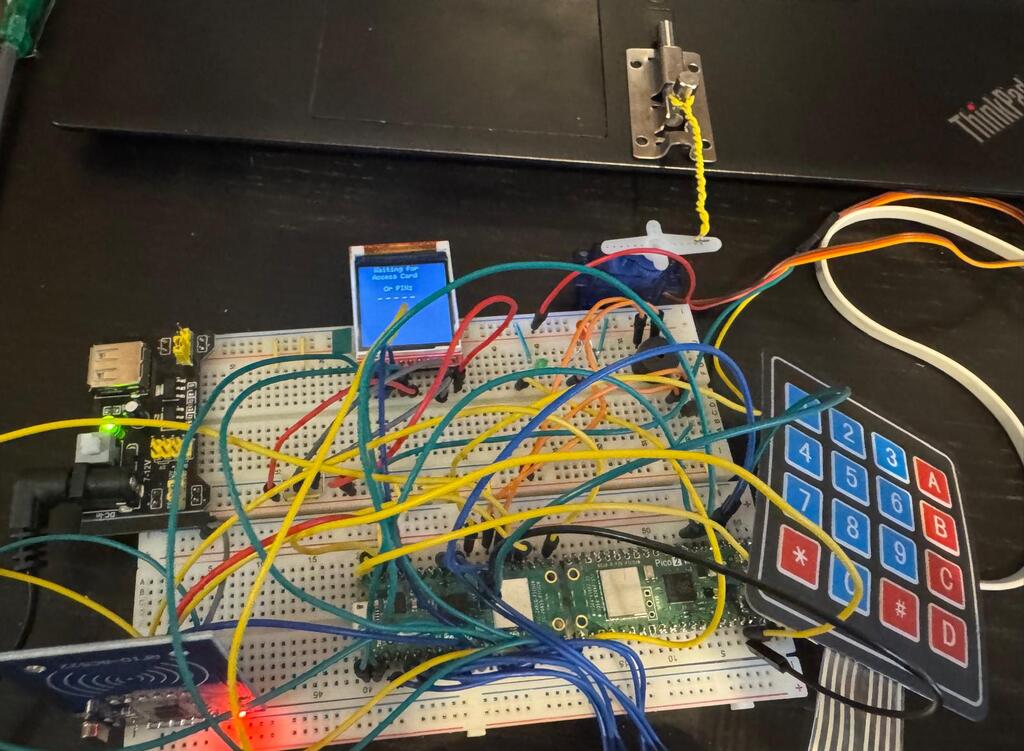
- Full locking cycle: The displays shows "Waiting for Access Card or PIN". The system unlocks in one of the 3 ways(RFID, PIN, WEB).Lights up the LED, plays a sound on the buzzer, shows "Access Granted" on the display, puts the servo motor in the unlocked position, pulling the door latch, shows a 5 second countdown on the LCD, then re-locks.
Week 19 - 25 May
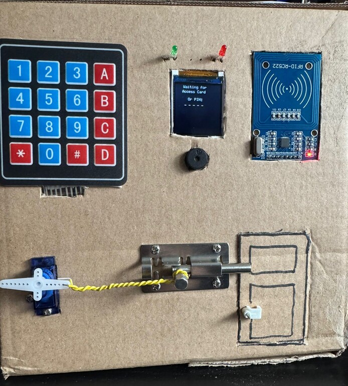
This week I focused on refining the project, improved reliability, interaction logic, UI, took out most of the components from the breadboards and put them into a cardboard box, displaying them nicely. The project is finished.
- Manual Locking Feature:
- Updated the PIN entry logic: now the system remains unlocked after a correct PIN, until the user presses * to lock it again.
- "*" is now excluded from the PIN itself and reserved exclusively as a locking command.
- Added a new button in the web interface (Lock) and now the web interface works like the pin, the unlock button keeps the servo unlocked until the user presses Lock
-
Redesigned the HTML to look cleaner, added the Lock button.
-
Added new LCD messages for the manual lock feature.
-
Got a cardboard box and carved holes of the same dimensions as the hardware components, wired them inside the box to the pico. Screwed the door latch and connected the servo to it, carved a small door to prove the functionality of the project.
Hardware
The hardware setup is centered around the Raspberry Pi Pico 2W, with its built-in Wi-Fi capabilities. A variety of peripherals are used to create an interactive, multi-authentication smart lock system.
Components Used
Raspberry Pi Pico 2W Central microcontroller; manages all logic and peripherals
Raspberry Pi Pico 2W Microcontroller configured as a debugger for the central Pico
RC522 RFID Reader SPI-based tag reader for user authentication
1.44inch SPI Module ST7735S Displays system messages over SPI.
4x4 Matrix Keypad Used to enter a PIN code for access
SG90 Micro Servo Motor Drives the door lock mechanism (via PWM control)
Active Buzzer Emits audio feedback upon certain actions (e.g. denied access)
LEDs Status indicator (access granted, access denied)
External 5V Power Source Provides sufficient current for the LCD and servo motor
Schematics
KiCad Scheme

Bill of Materials
| Device | Usage | Price |
|---|---|---|
| 2xRaspberry Pi Pico 2W | Main Controller & Debugger | 39.66 RON x2 |
| RFID RC522 | RFID Reader | 9,99 RON |
| 4x4 Keypad | PIN Insertion | 6.99 RON |
| Active Buzzer Module | Buzzer | 1.40 RON |
| Breadboard, Jumpers & Power Supply Kit | General Wiring & Voltage | 22.00 RON |
| 3 mm Diffused LED Diode Assortment Kit | LEDs & Resistors | 29.99 RON |
| SG90 Micro Servo Motor | Unlocking mechanism | 13.99 RON |
| 1.44inch SPI Module ST7735S | Status Display | 34.99 RON |
Software
| Library | Description | Usage |
|---|---|---|
| embassy-rp | Embassy HAL for Raspberry Pi Pico (RP2040) | Direct access and async control of peripherals like SPI, I2C, GPIO, and timers |
| embassy-executor | Async executor designed for embedded systems | Manages asynchronous task execution without needing an OS |
| embassy-time | Timekeeping and delay abstraction | Used for creating delays and timers without blocking |
| embassy-sync | Primitives for concurrency and synchronization | Enables mutexes, signals, and channels between async tasks |
| embassy-net | Async embedded TCP/IP network stack | Used to serve a web interface over Wi-Fi (for unlocking remotely) |
| cyw43 | Driver for the CYW43 Wi-Fi chip on the Pico 2W | Used to join a Wi-Fi network and host a small HTTP server |
| cyw43-pio | PIO SPI interface for CYW43 Wi-Fi chip | Interface for CYW43 to work over the RP2040’s PIO SPI |
| embedded-graphics | Drawing library for displays | Used to render text and countdowns on the LCD |
| mipidsi | ST7735s LCD display driver | Initializes and manages the LCD screen |
| mfrc522 | Rust driver for the MFRC522 RFID reader | Handles tag detection and UID reading |
| display-interface-spi | Abstraction layer for SPI display communication | Enables SPI-based display control |
| gpio | GPIO management | Used for controlling GPIO pins |
| heapless | Fixed-capacity collections for no_std | Used for String buffers and messaging |
| pwm | PWM module | Used for controlling the buzzer |