Polyphonic Keyboard Synthesizer
Embedded Rust on STM32
Project Documentation & Implementation Plan
Author: Delia Udrea
GitHub Project Link: https://github.com/UPB-PMRust-Students/project-dm-2025-DeliaUdrea
Description
This project aims to develop a fully functional digital musical instrument capable of rendering polyphony (chords) and responding in real-time to user interactions (keys, sustain pedal, pitch bend).
The core of the system is an STM32 Nucleo microcontroller, programmed in the Rust language (using a Real-Time framework) to guarantee minimal audio latency and high reliability.
Functionality
- Polyphonic Input: Reading approximately 61 keys (organized in an matrix) with anti-ghosting protection (diode per switch).
- Audio Synthesis: Digital generation of sound waves (sine/square) on the microcontroller, utilizing the DAC or PWM peripheral.
- Expressive Control: Implementation of the Sustain function (pedal) and Pitch Bend control (joystick).
- Audio Output: Amplifying the weak digital signal from the MCU to drive an external speaker.
Motivation
2.1 Project Motivation
- Technical Challenge: The project combines electronics (key matrix, audio filtering) with real-time programming, serving as an excellent demonstration of Rust capabilities in the
no_std(embedded systems) environment. - Experience Quality: The choice of high-quality mechanical switches (Outemu Linear, 65g) over simple buttons offers a superior feel suitable for a musical instrument.
- Practical Application: Creating a functional digital instrument capable of playing complete songs.
2.2 SWOT Analysis
| Strengths | Weaknesses |
|---|---|
High Performance: Rust no_std ensures minimal latency for real-time audio. | Complexity: Manually wiring a 61-key matrix is labor-intensive and error-prone. |
| Durability: Mechanical switches provide a robust and long-lasting interface. | Audio Quality: PWM synthesis is simpler but lower fidelity than a dedicated DAC chip. |
| Polyphony: Capable of playing multiple notes simultaneously (chords). |
| Opportunities | Threats |
|---|---|
| Scalability: The design can be expanded to include more effects (reverb, echo). | Component Availability: Specific switches or STM32 boards may be out of stock. |
| Educational: Deep dive into embedded systems, digital signal processing, and Rust. | Timing constraints: Real-time audio requires strict timing; missed deadlines cause glitches. |
Architecture
2.1 Hardware Architecture
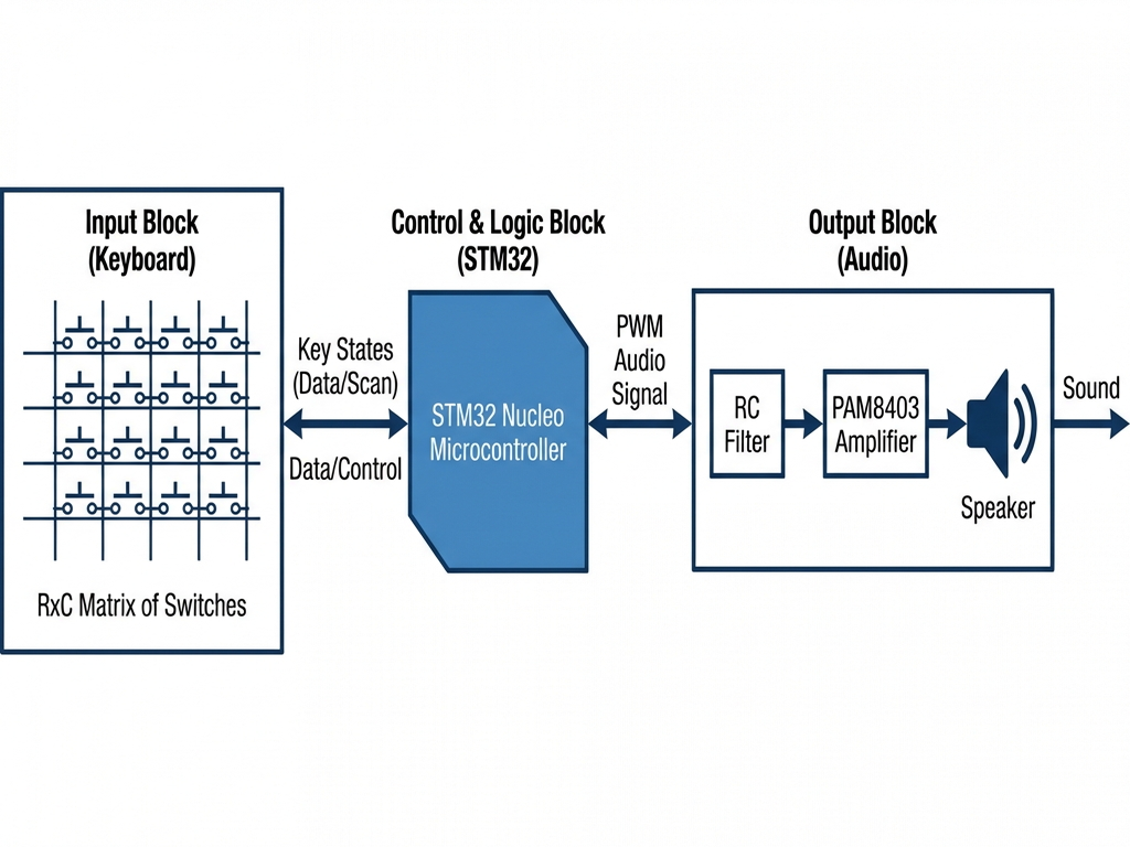
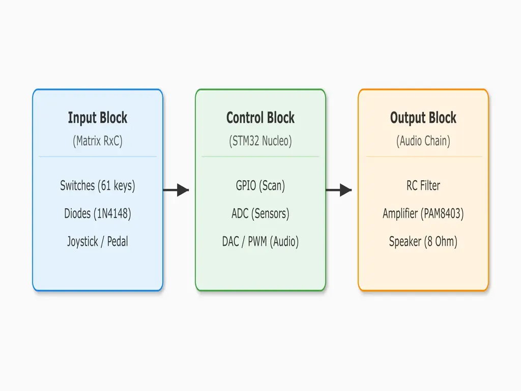
The system is divided into three main interconnected blocks:
- Input Block (Keyboard): The matrix of switches and diodes.
- Control and Logic Block (STM32): Processing input and generating the digital audio signal.
- Output Block (Audio): Filtering, amplification, and playback of the sound via the speaker.
Logical Interconnection Diagram:
2.2 Software Architecture
The software is built using Rust and the RTIC (Real-Time Interrupt-driven Concurrency) framework to manage the strict timing requirements of audio synthesis. The architecture binds strictly to the hardware peripherals to ensure zero-latency performance.
Concurrency & Priority Model
- Audio Task (Priority 2 - Critical): This is the "heartbeat" of the synthesizer. It is triggered by a hardware timer (e.g., TIM2) at exactly 44.1 kHz. Its sole responsibility is to calculate the next sample value and write it to the DAC/PWM output. It preempts any lower priority tasks to ensure no audio glitches occur.
- Logic Task (Priority 1): Triggered by software (Software Interrupt) whenever a key state changes. It handles the musical logic: converting key indices to MIDI notes, calculating frequencies using lookup tables (LUT), and processing Envelope (ADSR) states.
- I/O Task (Priority 0): A periodic scheduled task (approx. every 5ms). It handles the physical interface (Matrix Scanning and ADC polling).
Hardware Binding
The software interacts directly with the STM32F4 peripherals via the stm32f4xx-hal crate:
- GPIO (Key Matrix): The Key Scan algorithm dynamically reconfigures GPIO pins. It drives one Row pin High (Logic 1) and reads the Column pins. If a Column reads High, the switch at that intersection is closed. It iterates through all rows rapidly to detect multiple key presses.
- DAC / PWM (Audio Output): The system uses a hardware Timer to enforce the sample rate.
- PWM Mode: The timer controls the duty cycle of a high-frequency square wave (e.g., >200 kHz) to approximate an analog voltage through the RC filter.
- DAC Mode: The calculated digital sample (12-bit) is written directly to the DAC Data Holding Register (DHR), which converts it to voltage.
- ADC (Expressive Control): The Joystick and Pedal are connected to Analog Inputs. The code triggers an ADC conversion sequence and reads the raw 12-bit values (0-4095) to calculate Pitch Bend modulation and Sustain status.
Software Functional Diagram:
Log
This log tracks the project's progress, from component acquisition to the implementation of key functionalities.
Week 1: Planning and Hardware Acquisition
| Date | Status | Observations |
|---|---|---|
| Day 1-2 | Finalized BOM | Final confirmation of components (Outemu, PAM8403, 1N4148). |
| Day 3-5 | Workspace Setup | Installation of Rust toolchain (cargo-embed, probe-rs). |
| Day 6-7 | Hardware Design | Creation of logic schematic and interconnection diagram. |
| Status: | 90% Complete | Component acquisition is the priority. |
Week 2: Basic Tests and Soldering
| Date | Status | Observations |
|---|---|---|
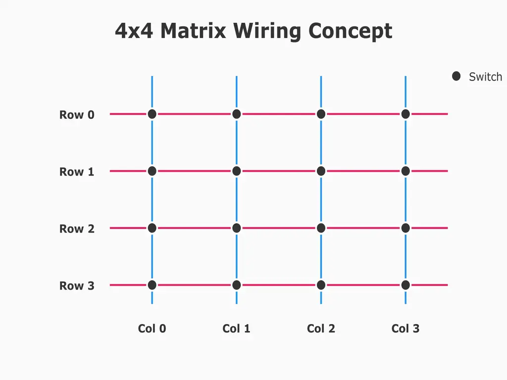
| Day 8-10 | Matrix Soldering (Ph.1) | Soldering first 20 diodes. Wiring 4x4 test matrix. |
| Day 11-12 | GPIO/Input Test | Rust code to scan 4x4 matrix and verify anti-ghosting. |
| Day 13-14 | Audio Output Test | Generating fixed frequency tone using DAC/PWM. |
| Status: | 30% Complete | Confirmation of basic input/output functionality. |
Week 3: Real-Time Implementation and Polyphony
| Date | Status | Observations |
|---|---|---|
| Day 15-17 | Audio Task | Implementing Audio Task at max priority (constant sample rate). |
| Day 18-20 | Polyphonic Synthesis | Modifying Audio Task for simultaneous notes/chords. |
| Day 21 | Final Assembly | Finalizing soldering of all ~61 keys. |
| Status: | 70% Complete | Basic piano functionality is finalized. |
Hardware
3.1 Critical Components
| Component | Specifications | Role in the Circuit |
|---|---|---|
| Microcontroller | STM32 Nucleo (e.g., F401RE) | Processing, Timers, ADC, DAC/PWM. |
| Switches | Outemu Linear (3-pin), 65g | Ensures quality tactile input. |
| Polyphony Diode | 1N4148 | Prevents "ghosting" in the matrix. |
| Amplifier | PAM8403 Module ( W) | Audio amplification from 3.3V to speaker level. |
| Matrix Wiring | Set 5 Spools 24 AWG | Stable, soldered wiring for the ~70 internal connections. |
3.2 Logical Interconnection Diagram
The hardware blocks connect to the STM32 peripherals as follows:
- STM32 Box: Handles GPIO, DAC/PWM, and ADC pins.
- Matrix: rows connect to GPIO (Output) and columns connect to GPIO (Input with Pull-up).
- Audio: Connection runs from the DAC/PWM pin, through the RC filter to the input of the PAM8403 module.
3.3 Detailed Electronic Schematic (KiCad)
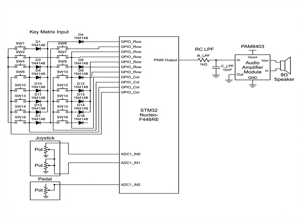
- Key Matrix: connection with each diode (1N4148) correctly oriented on each switch.
- Audio Filter: Resistor and capacitor (RC Low-Pass Filter) needed to smooth the PWM signal.
3.4 Prototyping and Wiring
- Matrix Construction: Will be built by manually soldering the 24 AWG cable to the output pin of each switch.
- Termination: The approx 20 wires from the matrix will be soldered onto the 20-pin IDC Connector.
Bill of Materials
Estimates based on average market rates (RON).
| No. | Component | Specifications | Qty | Unit (RON) | Total |
|---|---|---|---|---|---|
| HARDWARE | |||||
| 1. | Microcontroller | STM32 Nucleo (F401RE) | 1 | 80.00 | 80.00 |
| 2. | Key Switches | Outemu Linear, 65g | 70 | 1.80 | 126.00 |
| 3. | Diode Kit | 1N4148 (20 pcs/kit) | 4 | 12.00 | 48.00 |
| 4. | Audio Amplifier | PAM8403 (2 x 3W) | 1 | 25.00 | 25.00 |
| 5. | Speaker | 4 inch, 8 Ohm | 1 | 40.00 | 40.00 |
| 6. | Sustain Button | Momentary Pushbutton | 1 | 10.00 | 10.00 |
| PROTOTYPING | |||||
| 7. | Protoboard | Breadboard MB102 | 1 | 20.00 | 20.00 |
| 8. | Jumper Wires | Male-Male | 1 set | 15.00 | 15.00 |
| 9. | Matrix Wire | 24 AWG Cable | 1 set | 30.00 | 30.00 |
| 10. | Matrix Conn. | IDC 20 pin | 1 | 10.00 | 10.00 |
| 11. | Speaker Cable | 2 x 0.75 mm^2 | 1 m | 5.00 | 5.00 |
| TOOLS | |||||
| 12. | Soldering Kit | 60W Iron + Stand | 1 set | 125.00 | 125.00 |
| 13. | Resistor Kit | 600 pcs | 1 set | 45.00 | 45.00 |
| 14. | Capacitor Kit | 500 pcs | 1 set | 50.00 | 50.00 |
| TOTAL ESTIMATED | ~ 619 |
Software
5.1 Detailed Software Architecture
The system relies on a concurrent architecture, likely using RTIC or Embassy to ensure real-time responsiveness.
| Task | Function | Priority | Description |
|---|---|---|---|
| Audio Gen | Audio Output | Max (Critical) | Runs at ~44 kHz, feeding DAC/PWM. Must not be interrupted. |
| Key Scan | Matrix Input | Medium | Scans matrix (1-5 ms) to detect key presses. |
| Control | Musical Logic | Medium | Calculates Hz and Volume, manages Sustain/Pitch Bend. |
| Idle | Debugging | Low | Sends debugging messages to PC (RTT). |
5.2 Shared Data Structure (Safety in Rust)
To prevent data races, all data accessed by both the Audio Task and the I/O Task is protected.
- Active Notes: A vector or array (e.g.,
Vec<NoteData>) storing currently active notes. - Protection: Protected by critical sections (RTIC) or channels (Embassy).
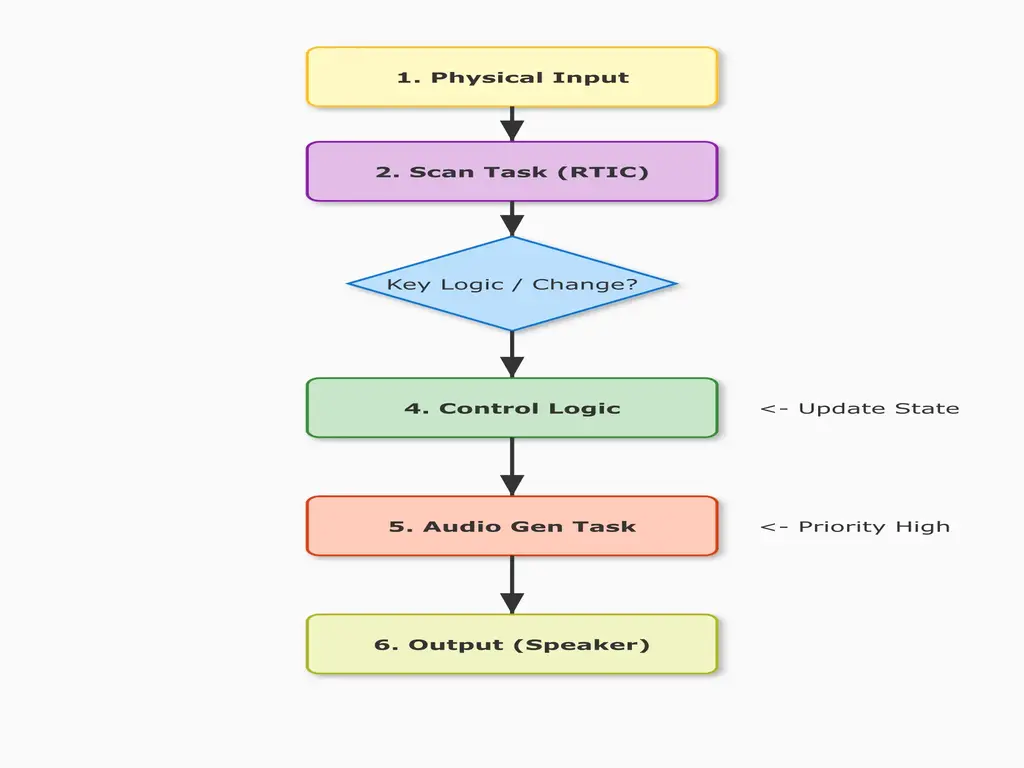
5.3 Functional Diagram (Data Flow)
- Physical Input: Switches, Joystick, Pedal.
- Scan Task: Matrix is scanned ADC pin is read.
- Key Event: NoteOn / NoteOff sent to Musical Logic.
- Control Logic: Determines Freq/Amp, updates shared structure.
- Audio Gen Task: Reads shared structure, calculates wave value.
- Output: Digital signal Filter Amp Speaker.