Smart Door
A Raspberry Pi Pico 2 W based door security system.
Author: Octavian Mihai Cretu
GitHub Project Link: https://github.com/UPB-PMRust-Students/project-octavian2411
Description
This project aim is to develop a smart door lock system powered by a Raspberry Pi Pico 2 W. It uses a fingerprint sensor to authenticate users, a servo motor to simulate locking and unlocking the door, and a buzzer to signal access. An LED display shows real-time status messages, while an ultrasonic sensor monitors the door's open or closed state. The system combines biometric security with sensor-based monitoring to create an interactive and responsive door locking simulation.
Motivation
I chose this project because I’ve always found fingerprint matching really interesting. The idea that you can use something as unique as a fingerprint to unlock a door seemed like a fun and useful concept to explore. I wanted to learn how to use a fingerprint sensor with a microcontroller and see how everything works together. This project also lets me combine different parts like a servo motor, buzzer, LED display, and ultrasonic sensor to create a full system. By using the Raspberry Pi Pico 2 W programmed in Rust, I’m gaining a better understanding of how Rust works in embedded systems, especially with its concurrency features, and async behavior for handling multiple tasks efficiently.
Architecture
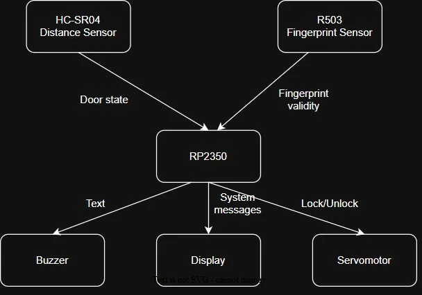
-
Authentication Module
- Handles fingerprint scanning and matching.
- Communicates with the fingerprint sensor over UART.
- Sends authentication results (success/failure) to the Control Module.
-
Control Module
- Core decision-making unit of the system.
- Receives input from the Authentication Module and Sensor Interface.
- Controls actuators (servo, buzzer) and updates the display.
- Manages system states such as Locked, Unlocked.
-
Sensor Interface
- Reads distance data from the ultrasonic sensor using GPIO.
- Determines if the door is open or closed.
- Sends door state updates to the Control Module.
-
Actuator Interface
- Controls output devices.
- Servo Motor via PWM for locking/unlocking.
- Buzzer via GPIO or PWM for alerts.
-
Display Interface
- Updates the LED display with system status messages (e.g., "Locked", "Access Granted").
- Communicates with the display using I2C.
Log
Week 10 - 28 April
Assembeled componenets on a breadboard and tested how they all work separately.
Started working on interfacing with the R503 fingerprint sensor
Hardware
Raspberry Pi Pico 2 W:
- Central microcontroller that manages all inputs, outputs, and logic.
- Runs the program written in Rust.
Fingerprint Sensor (R503):
- Authenticates users by matching scanned fingerprints with stored data.
- Communicates with the Pico via UART.
Servo Motor:
- Simulates the physical locking and unlocking of the door.
- Controlled via a PWM signal from the Pico.
Ultrasonic Distance Sensor (HC-SR04):
- Detects if the door is open or closed by measuring distance.
- Uses GPIO pins for trigger and echo.
LED Display (LCD 1602 - I2C):
- Shows system status messages like "Locked", "Access Granted", or "Register Fingerprint".
- Communicates with the Pico via I2C.
Buzzer:
- Sounds a short alert when the door is unlocked or about to be locked.
- Controlled via PWM.
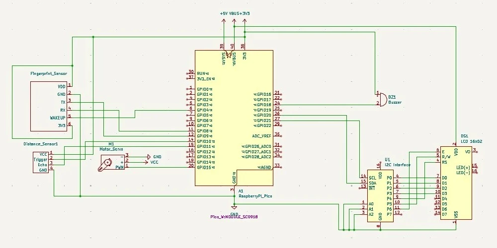
Schematics
Bill of Materials
| Device | Usage | Price |
|---|---|---|
| Raspberry Pi Pico 2 W | The microcontroller with Wi-Fi for phone notification | 39.50 lei |
| R503 - Fingerprint Sensor | For fingerprint detection | 132 lei |
| LCD1602 - I2C | Displays system messages | 16 lei |
| HC-SR04 Ultrasonic Distance Sensor | For measuring distances to door | 6.50 lei |
| SG90 Micro Servo Motor | For simulating locking mechanism | 14 lei |
| Passive Buzzer Module | For audible alerts | 1.50 lei |
| Wires + Breadboard | For connections | 15 lei |
Software
| Library | Description | Usage |
|---|---|---|
| embassy-rp | Hardware Abstraction Layer | Interfaces with Raspberry Pi Pico 2 W hardware |
| embassy-executor | Task executor | Handles asynchronous tasks |
| embassy-time | Timing module | Provides timing functions for operations |
| lcd1602-driver | LCD1602 Interface | Communication with the display |
| pwm | PWM Module | For buzzer and servo |
| uart | UART Module | For fingerprint senzor |