Educational PID Demonstration
A visual representation of Control System application: a moving arm.
Author: Gabriela-Florentina Alexa
GitHub Project Link: https://github.com/UPB-PMRust-Students/project-Eiline04
Description
The project I am about to make has the purpose of illustrating PID principles, using an ESP32 WROOM to balance a fan-powered arm. The system consists of a distance sensor used to follow the hand of the user. For educational purposes, I am also going to use a gyroscope in order to get stability feedback. Furthermore, the fan is moved with a brushless motor (which is connected to the microcontroller via an ESC - electronic Speed Controller). Thus, this project has a high impact on demonstrating how a real-time control system works.
Motivation
My interest in PID control began in high school, when I first used it to optimize the trajectory of an autonomous robot (as I was part of a robotics team). Since then, I've been fascinated by how control systems are applied in everyday life-whether in cars, drones, or even household appliances like thermostats. This project allows me to dive deeper into a topic I find both intellectually challenging and personally rewarding. By combining sensors, real-time feedback, and control algorithms, I aim to better understand and illustrate the principles behind modern automation. I am excited to help the 16 y.o. version of me understand the 'magic' behind the programming tools she had used in high school, but also create a visual representation of a very cool principle, so that others can understand it too.
Architecture
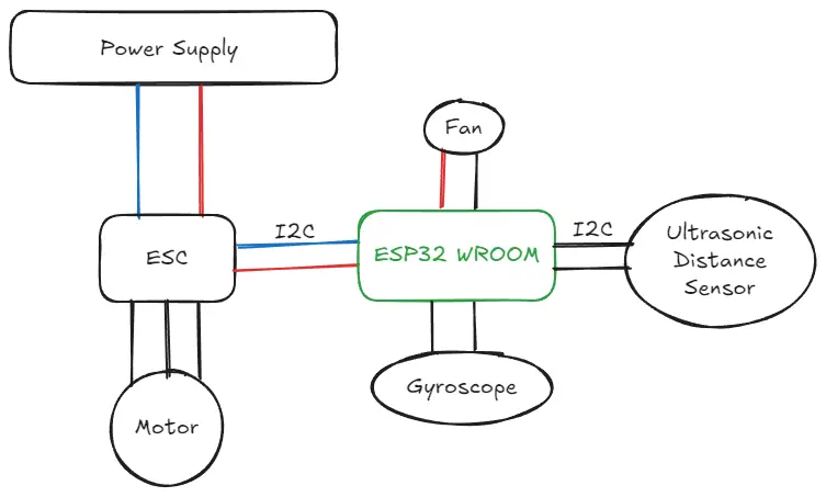
The architecture of the system is designed to demonstrate PID control principles in a real-time environment. The main components of the architecture are:
- Sensor System: A distance sensor detects the user's hand position, acting as the system input.
- Controller: An ESP32 WROOM microcontroller runs the PID algorithm and processes data from the sensors (gyro and distance sensor).
- Feedback System: A gyroscope provides real-time orientation data for stability feedback. It will also provide data that can be used to draw informative graphics.
- Actuator System: A brushless motor, connected to the ESP32 via an ESC (Electronic Speed Controller), adjusts the fan's thrust to balance the arm.
- Power Supply: Delivers sufficient current (~20A) to drive the motor. (It has bult-in off swith in case of danger)
- Cooler: Makes sure the ESC is not overheating (althought it is very unlikely to heat, as I am going to use 20-30A).
These components are interconnected to form a closed-loop control system that continuously adjusts the fan thrust to maintain balance (to keep the arm at a constant position) based on the data provided by the distance sensor.
Log
Week 5 - 11 May
Week 12 - 18 May
Week 19 - 25 May
Hardware
Hardware
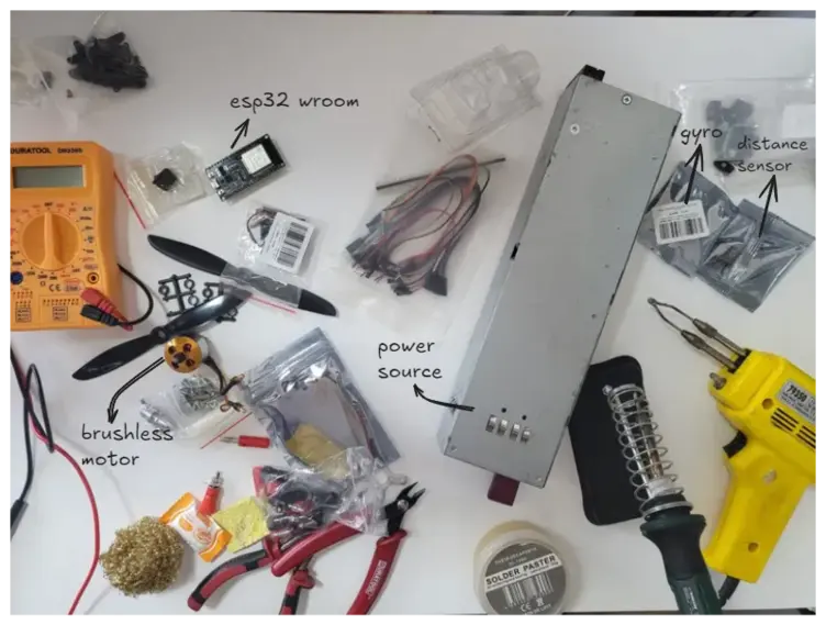
The project uses the following hardware components:
- ESP32 WROOM: Core microcontroller for real-time PID control logic.
- VL53L0X Distance Sensor: Detects the position of the user's hand (I²C).
- MPU6050 Gyroscope: Provides angular velocity and acceleration data for stability feedback (I²C).
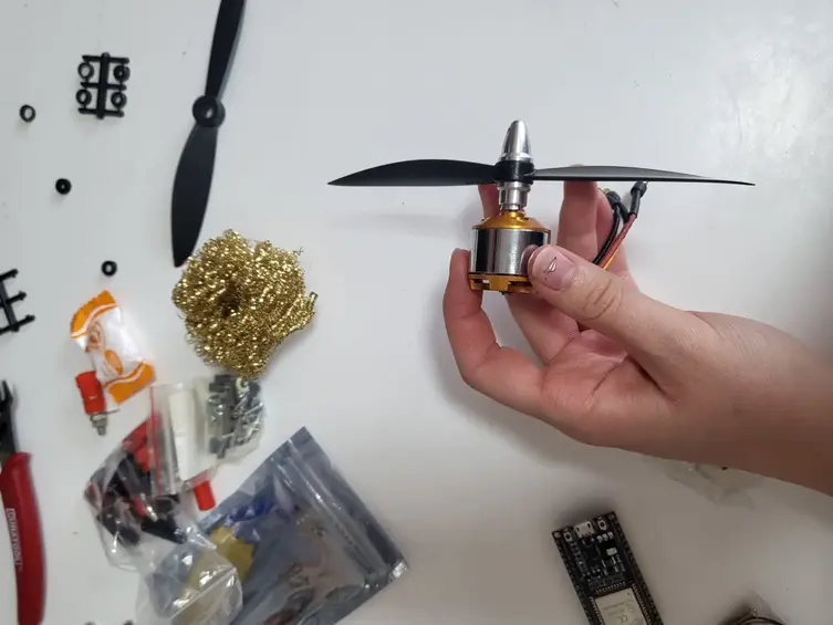
- Brushless Motor (BLDC) + ESC (Electronic Speed Controller): Acts as the actuator that drives the fan to balance the arm, controlled via PWM from the ESP32.
- Cooler (Fan): Controlled via a GPIO pin to prevent overheating.
- Power Source (12V / 20A): Powers the ESC -> brushless motor.
- Physical Frame (wood/cardboard): Holds all components and supports the motion of the balancing arm.
Components and materials - Photos
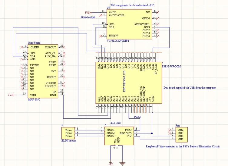
Schematics
Bill of Materials
| Device | Usage | Price |
|---|---|---|
| ESP32 WROOM Dev Board | Main microcontroller | 40.00 RON |
| GY-521 (MPU6050) | Gyroscope and accelerometer module | 24.16 RON |
| VL53L0X Time-of-Flight Sensor | Measures distance to user's hand | 16.76 RON |
| ESC 30A | Controls brushless motor | 47.15 RON |
| Brushless Propeller Set 6045 CW/CCW | Attached to motor for thrust | 9.84 RON |
| Brushless Motor (BLDC) | Keeps the hand in needed position. | 45 RON |
| 5V Fan (Raspberry Pi, 3030) | Used as a cooler | 8.04 RON |
| 4mm Banana Connector (Female, Red) x3 | Power connection | 5.22 RON |
| 4mm Banana Connector (Female, Black) x3 | Ground connection | 5.22 RON |
| 4mm Banana Connector (Male, Red) x3 | Power cable end | 2.94 RON |
| 4mm Banana Connector (Male, Black) x3 | Ground cable end | 2.94 RON |
| [Hinge](physical shop) | Makes the arm mobile. | 8 RON |
Total estimated cost: ~215 RON
Software
| Library | Description | Usage |
|---|---|---|
embassy-rs | Asynchronous embedded framework | Handles async tasks on the ESP32 |
esp-idf-sys | Rust bindings for ESP-IDF | Enables low-level interaction with ESP32 |
i2cdev | I2C device communication | Communicates with distance sensor and gyroscope |
pwm | Pulse Width Modulation | Controls ESC for motor speed |
serialport | Serial communication | Debugging and data logging |
Links
- PID Explained – Useful introduction to PID control.
- Idea – From here I have the project idea.
- ESP32 & BLDC Motor – Useful tutorial.