PicoReflex F1 Edition
A reflex training game built on a Raspberry Pi Pico 2W, housed in an F1-inspired 3D-printed enclosure.
Author: Sahnoun Taher
GitHub Project Link: https://github.com/UPB-PMRust-Students/fils-project-2026-taherdaringa-maker
Description
PicoReflex F1 Edition is a reflex training game inspired by the reaction time demands of Formula 1 racing. The device uses a Raspberry Pi Pico 2W running async Rust with Embassy-rs. The player must react to a randomly triggered LED signal by pressing the corresponding button as fast as possible. The system measures reaction time in milliseconds, displays the result on an OLED screen, and provides audio feedback via a buzzer. Results are tracked across sessions and accessible over WiFi.
Motivation
I chose this project because it combines all the core concepts covered in the MA course — GPIO, PWM, ADC, SPI, I2C, async Embassy, and WiFi — into a single functional device. The F1 theme reflects my personal interest in motorsport and gave me a creative direction for the enclosure design. Building a reflex trainer also has real practical value for anyone looking to measure and improve their reaction time.
Architecture
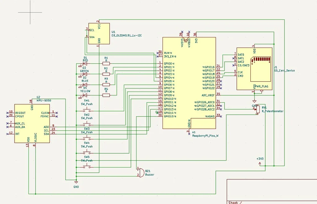
The Raspberry Pi Pico 2W acts as the central controller, coordinating all peripherals:
- GPIO — buttons for player input and LEDs for stimulus signals
- PWM — buzzer for audio feedback on correct/incorrect reactions
- ADC — potentiometer for difficulty/sensitivity adjustment
- SPI — OLED display for showing reaction times and scores
- I2C — MPU6500 sensor integration
- Async Embassy — concurrent task handling for timers, input, display, and WiFi
- WiFi — score reporting and remote leaderboard access
Weekly Log
Week 1 - Project Setup & Hardware Planning
- Defined project concept: PicoReflex GP, an F1-inspired reaction-time game console
- Selected main hardware: Pico 2W, OLED, MPU sensor, LEDs, buttons, buzzer, potentiometer, SD card module
- Planned game modes: Classic, Survival, Tilt, Sequence, Ghost, and Race
- Set up Rust project structure and initial embedded dependencies
Week 2 - Basic Hardware Bring-up
- Tested LEDs, buttons, buzzer, and OLED separately
- Fixed OLED I2C timing issues using slower I2C and timing register tweaks
- Confirmed button wiring with internal pull-ups
- Added basic reaction-time display on OLED
Week 3 - Core Game Modes
- Implemented Classic mode with random LED, button input, reaction time, lives, and rounds
- Added Survival mode with decreasing timeout
- Added Tilt mode using MPU accelerometer directions
- Added hearts, round display, win/lose screens, average reaction time, and buzzer feedback
Week 4 - Difficulty & Extra Modes
- Added potentiometer-based difficulty with three levels: Easy, Medium, Hard
- Added Sequence mode with LED pattern memory gameplay
- Added Ghost mode with saved best scores per difficulty
- Added erase controls for Ghost records using mode button + game buttons
Week 5 - SD Card & Persistence
- Tested SD card communication over SPI-style GPIO pins
- Switched to raw SD sector storage after FAT-style writing was unreliable
- Saved Race leaderboard, player names, run count, last score, and Ghost records
- Verified saved data survives unplug/replug when SD wiring is stable
Week 6 - WiFi Dashboard & Race Mode
- Added Pico 2W WiFi dashboard hosted directly from the Pico
- Created Race mode with one fixed difficulty for fair public competition
- Added live leaderboard with editable player names
- Improved dashboard for phone use and reduced refresh rate to avoid overloading Pico WiFi
Week 7 - Final Polish & 3D Enclosure
- Added 3-2-1 START countdown before games
- Improved OLED screens with hearts, difficulty bars, Ghost best display, and small visual accent
- Added final Ghost hard mode mixing button, tilt, and sequence challenges
- Designed and built the 3D enclosure for the console
- Adjusted wiring layout to fit inside the printed case and prepared final assembly for presentation
Hardware
The project is built around the Raspberry Pi Pico 2W (RP2350) which provides GPIO pins, SPI/I2C peripherals, ADC inputs, and onboard WiFi. An OLED display shows reaction scores. LEDs serve as stimulus signals and buttons capture player input. A buzzer provides audio feedback. A potentiometer allows difficulty adjustment. A MicroSD card stores session scores. Everything is housed in a custom F1-inspired 3D-printed enclosure.
Schematics
Bill of Materials
| Device | Usage | Price |
|---|---|---|
| Raspberry Pi Pico 2W | The microcontroller | borrowed |
| Raspberry Pi Pico 2 | Debugging probe | 48.40 RON |
| OLED Display 0.96" I2C | Displays reaction time and score | 16.96 RON |
| MPU6500 Accelerometer Gyroscope I2C | Motion sensor | 11.99 RON |
| MicroSD Module | Score storage | 4.38 RON |
| Passive Buzzer 5V | Audio feedback | 1.45 RON |
| LED 5mm Red | Stimulus signal | 0.30 RON |
| LED 5mm Yellow | Stimulus signal | 0.30 RON |
| LED 5mm Green | Stimulus signal | 0.30 RON |
| LED 5mm Blue | Stimulus signal | 0.30 RON |
| Push Buttons 6x6x5 x5 | Player input | 1.80 RON |
| Potentiometer RK097N 10K | Difficulty adjustment | 3.03 RON |
| Resistors 1K x20 | Current limiting for LEDs | 3.19 RON |
| 40 Dupont Wires 10cm | Connections | 7.73 RON |
| Breadboard 830 points | Prototyping | 10.00 RON |
| Micro USB Cable | Power | 4.36 RON |
| HAMA 124151 MicroSDHC 32GB Class 10 | Score and data storage | 58.99 RON |
| Total | ~176 RON |
Software
| Library | Description | Usage |
|---|---|---|
| embassy-rp | Async HAL for RP2350 | Peripheral drivers for GPIO, PWM, ADC, SPI, I2C |
| embassy-executor | Async task executor | Runs concurrent tasks for input, display, buzzer, WiFi |
| embassy-time | Async timers and delays | Measures reaction time in milliseconds |
| embassy-sync | Channels and mutexes | Shares state between async tasks |
| cyw43 | WiFi driver for Pico 2W | Enables network connectivity for score reporting |
| ssd1306 | OLED display driver | Shows reaction times and scores over I2C |
| embedded-graphics | 2D graphics library | Renders text and graphics on the OLED display |