Smart Training Station
A smart reaction-training station that uses lights and sensors to measure hit force while logging scores online in real-time.
Author: Cucerave Adelina-Maria 1222EEB
GitHub Project Link: https://github.com/UPB-PMRust-Students/fils-project-2026-AdelinaMariaCucerave
Description
This project is an interactive training station that uses a network of sensors to track physical hits and share the results over the internet. The system is built with several "interaction nodes" that connect to a main controller and a central dashboard.
The station works by using piezo sensors to measure exactly how hard and how fast a user hits a target. Because hitting these sensors can create high-voltage spikes, the system includes a protection circuit (Schottky-clamping). This keeps the sensitive electronics safe while ensuring the hit data is recorded accurately.
Users get instant feedback through three different channels:
-
Visual: Bright RGB LED rings change colors to show the intensity of the hit.
-
Audio: A buzzer plays different sounds for successful hits or errors.
-
Data: A color screen displays live scores and menus, while a knob (potentiometer) lets the user manually adjust how sensitive the sensors are.
The "brain" of the system is the STM32U545RE-Q microcontroller. It runs on a modern software framework called Embassy-rs, which allows the code to handle many tasks at once without slowing down. Finally, an ESP32-C3 Wi-Fi module acts as a bridge, sending the performance data to an online dashboard so users can track their progress over time.
Motivation
I have always been interested in how technology can be used to measure and improve human performance. Reaction time and physical precision are important in many areas, such as professional sports, physical therapy, and even industrial safety.
By building a system that gives instant feedback through lights and sounds, users can train their reflexes in a more engaging and effective way. Additionally, by adding Wi-Fi connectivity to the station, performance data can be tracked and saved over time. This allows users to stay aware of their progress, set personal goals, and find specific areas where they can improve their speed and accuracy.
Architecture
Main Architectural Components:
-
Signal Acquisition Unit (Input)
Role: Detects physical impacts and measures the force of each hit.
Components: 3x Piezo Diaphragms and 1x Potentiometer (used for adjusting sensor sensitivity).
-
User Interface and Dashboard (I/O)
Role: Manages the menu system and displays live scores and training data.
Components: 1.8" SPI TFT Display and 3x Tactile Push Buttons (for navigation and selection).
-
Haptic Feedback System (Output)
Role: Provides immediate visual and audio alerts to the user when a target is hit.
Components: 3x 16-LED RGB Rings and a Passive Buzzer.
-
Wireless Telemetry Bridge (Connectivity)
Role: Sends performance results and hit data to a remote web dashboard via Wi-Fi.
Components: ESP32-C3 (RISC-V) Module.
Log
Week 5:
- Research, decided on an idea
- Asked lab assistant about it, decided to improve it
Week 6:
- Started to look at components
- Decided on what I wanted to buy
Week 7:
- Waited for lab feedback
- Placed the order
Week 8:
- Some components came, started to look into Ubuntu for this assignment
- Having problems with Windows/Linux environment but fixing them
- Received help with soldering some wires to my piezo sensors and RGB LED rings
Week 11:
- Finished with KiCAD schematic
- Noticed 2 things when testing the protection circuit for the piezoel. sensors: I need a different capacitor ( 100nF instead of 200nF), missing FTF wires
- I also need a different potentiometer because the legs of the one I have right now are too short to reach into the breadboard, ordered it
Week 12:
- Will start doing testing of hardware
- Started thinking about software structure
Week 13:
- Started writing the skeleton of the code, haven't yet figured how to upload it to the private github page
- Realised one piezo might be broken, no time to replace it
- Rest of the pieces I needed arrived
Week 14:
- Piezo sensors and LED rings work (sort of), there is still a lot of optimization to be done
Hardware
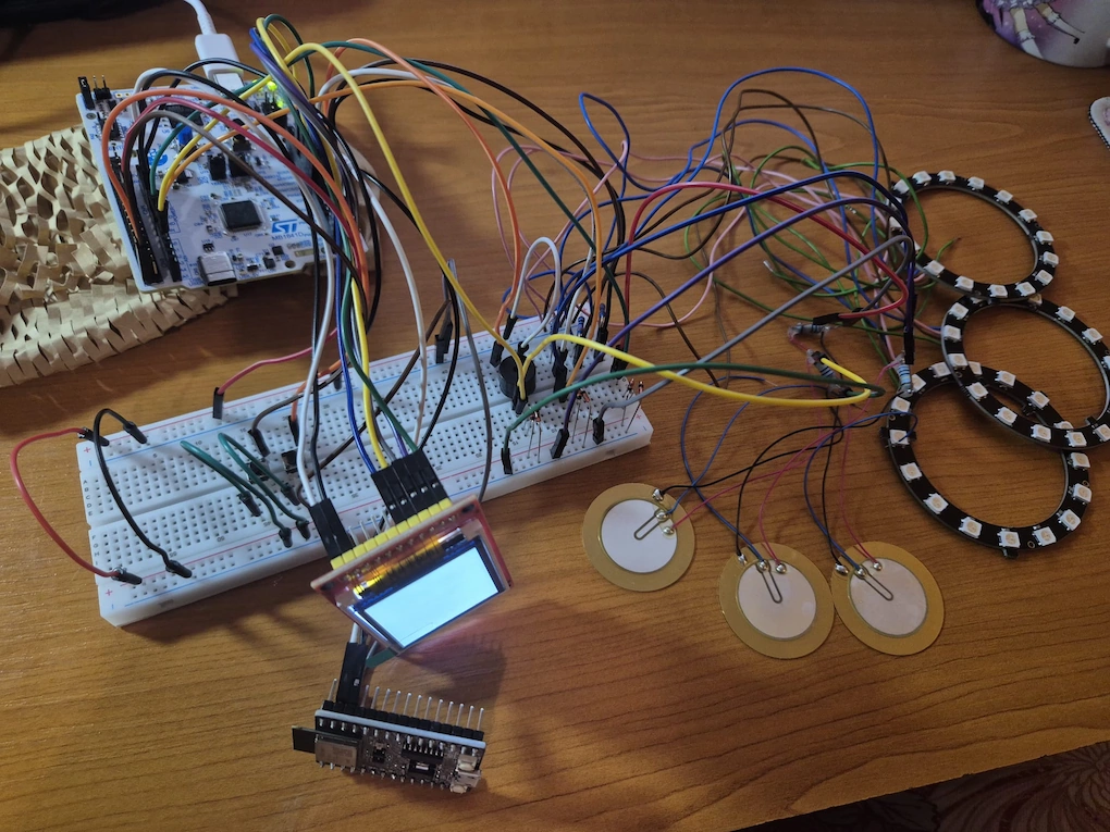
The main component is the Nucleo STM32U545RE-Q board that acts as the central unit, analyzing real-time vibration data based on signals from three piezoelectric diaphragms taped underneath the training cups. To protect the microcontroller's ADC pins from high-voltage spikes caused by physical "thumps," each piezo is connected through a protection circuit using BAT41 Schottky diodes and high-value resistors. A potentiometer is integrated to provide a variable voltage signal, allowing the user to manually adjust the "Global Sensitivity" threshold for the training session.
For user feedback, the STM32 controls RGB LED rings to provide instant visual cues—turning green for a perfect hit, yellow for soft, and red for too hard—while a passive buzzer is tied to a PWM channel to generate audible warning tones. Detailed performance data, including reaction latency and impact force percentage, is transmitted via SPI to the display, which serves as a real-time scoreboard. Finally, the ESP32-C3 module handles Wi-Fi and Bluetooth connectivity, allowing the training data to be transmitted wirelessly for long-term progress tracking.
Schematics


Bill of Materials
| Device | Usage | Price |
|---|---|---|
| STM32U545RE | The microcontroller | 107 RON |
| 4 * 35mm Piezoelectric Diaphragm Sensor | Sensor to convert physical thumps to electrical signals | 47 RON |
| 12 * Schottky Diodes | Part of protection circuit to protect from high-voltage spikes from sensors(I might get a voltage stabilizer but I don't know yet) | 12.84 RON |
| 6 * 10M Ohm Resistors | Resistors for piezo sensors | 13 RON |
| 20 * 220M Ohm Resistors | Resistors for LEDs | 3.42 RON |
| 20 * 330M Ohm Resistors | Resistors for LEDs | 2.6 RON |
| 2 * Potentiometer | For adjusting sensitivity threshold of sensors | 7.52 RON |
| 10 * RGB LED | Visual color feedback (I bought simple LEDs as a backup in case the rings don't work) | 10 RON |
| 10 * Push Buttons | User input for the display | 3.6 RON |
| 6 * Capacitor | Part of protection circuit to protect from high-voltage spikes from sensors | 3.54 RON |
| 2 * Passive Buzzers | Audio feedback (success/failure) | 2 RON |
| 4 * RGB LED Rings (link is not the same one) | Visual color feedback | 38.36 RON |
| ESP32-C3 | Wi-Fi communication | 34 RON |
| Breadboard + Jumper Wires | Connecting components | 34 RON |
| ST7735 1.8" TFT LCD Display Screen | Display for scoreboards | 64.59 RON |
| ~20 MTM Jumper Wires | Connecting components | 15.74 RON |
| ~40 MTM Jumper Wires (different lengths) | Connecting components | 21.63 RON |
| 40 MTM Jumper Wires | Connecting components | 10 RON |
| 40 MTF Jumper Wires | Connecting components | 10 RON |
| **I bought many spares because this is my first project and I might need them if I break something + many other components like jumper wires for future components (also bought from different sites because of quality differences) |
Software
| Library | Description | Usage |
|---|---|---|
| stm32u5xx-hal | Used for STM32 | ADC for piezos, PWM for the buzzer, GPIO for LEDs etc. |
| embedded-graphics | 2D graphics library | Drawing, scoreboard, percentage bars to the display. |
| embedded-hal | Embedded hardware | "Translator" between sensor code and the screen/peripherals. |
| cortex-m-rt | ARM Cortex-M | Tells the processor how to start up and manage the basic execution loop. |
| st7735-lcd | Driver for the 1.8" TFT LCD | Sending pixel data to screen. |
| nb | Non-blocking multitasking support | Checking for "thumps" while simultaneously running the game timer. |
| micromath | Fast math operations | Converting raw electrical spikes into force percentages to display on screen. |
| heapless | Memory-efficient data structures | Storing high scores or last hits without using dynamic memory. |
| panic-probe | Panic handler | Error debugging. |
| **TBC |
Software Description
For the software architecture, I chose to implement an event-driven system using the embassy-rs asynchronous framework. This allows the STM32 microcontroller to handle multiple tasks concurrently without blocking. Rather than relying on shared global variables (can lead to memory safety issues and tight coupling) the system uses "message passing". Independent tasks communicate exclusively by sending data through strictly typed asynchronous channels. Because of this, for ex if the TFT display takes a few milliseconds to draw a frame, it never blocks the sensing tasks from instantly registering a new physical hit.
The system is strictly divided into three modular layers: Input, Logic, and Output. The Input layer acts as the sensory node; dedicated tasks continuously sample raw ADC values from the piezoelectric sensors, filter out electrical noise, and fire clean "HitEvents" into the system's channels. The Logic layer serves as the central brain, where the main game task listens for these events, evaluates them against the timing and scoring rules, and dispatches commands. Finally, the Output layer acts as the hardware translator. Dedicated peripheral tasks sit idle until commanded, utilizing Direct Memory Access (DMA) and SPI to blast complex visual data to the WS2812 LED rings and the ST7735 screen without taxing the main processor. This approach ensures that the hardware remains completely independent from the core game logic.