Reaction Time Game
A microcontroller-based game that measures user reaction speed
Author: Circiumaru Octavian-Cristian
GitHub Project Link: https://github.com/UPB-PMRust-Students/fils-project-2026-TaviCirciumaru
Description
Reaction Time is an embedded system game that measures how fast a user reacts to a signal. The system waits for a random delay, then prompts the user with visual and auditory signals, measuring the time taken to respond.
Motivation
I chose this project to explore how human reaction time works and how it can be accurately measured using an embedded system. Reaction time is an important indicator in many real-world scenarios, from gaming and sports to driving and safety-critical systems. By implementing this project, we can better understand how delays, stimuli, and user responses interact in real time.
Architecture
The system is composed of several logical components:
- Input Handler: manages push button inputs (start, reaction, reset)
- Game Logic Controller: handles game states (idle, waiting, signal, result, false start)
- Timing Module: measures reaction time using hardware timers
- Display Module: outputs instructions and results to the LCD
- Signal Module: controls LED and buzzer for user prompt
- Random Delay Generator: creates unpredictable wait times before signal

Log
Week 4
- Thought about project ideas and researched about required hardware components.
Week 6
- Received project feedback and the components arrived.
Week 7
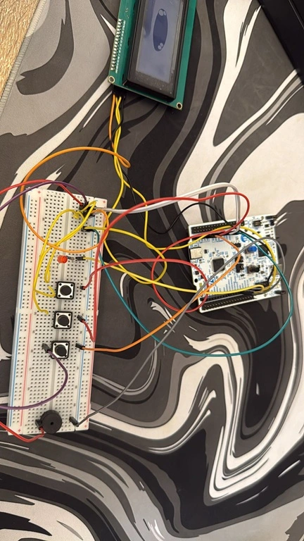
- Started testing the components.
- Built an initial circuit to connect the STM to the LCD screen.
Week 9
- Work on documentation and software part of the project.
Hardware
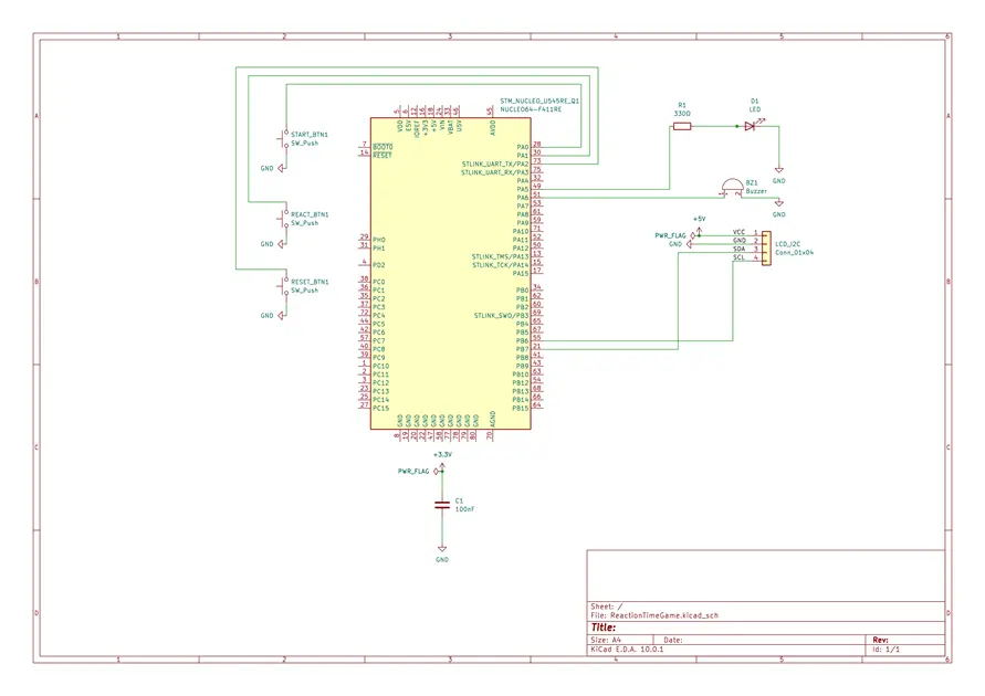
The system is built around the STM NUCLEO-U545RE-Q microcontroller, which manages inputs, timing, and outputs. The user interacts with the system using three push buttons connected to GPIO pins, while feedback is provided through a 20x4 I2C LCD display, a LED (with current-limiting resistor), and a buzzer. All components are connected on a breadboard using jumper wires (M-M, M-F), with additional resistors for stability and decoupling capacitors for reliable operation. Communication is handled via GPIO and I2C, and the system is powered and programmed through the USB (ST-Link) interface.
Schematics
Bill of Materials
| Device | Usage | Price |
|---|---|---|
| STM NUCLEO-U545RE-Q | Main microcontroller board | 125 RON |
| Hitachi HD44780 LCD I2C (20x4) | Display instructions and results | Already owned |
| Push Buttons (x3) | User input control | 20 RON |
| Buzzer (x1) | Audio signal | Already owned |
| LED | Visual signal | Already owned |
| Resistors | Circuit stability | ~ 10 RON |
| Breadboard & Jumper Wires | Prototyping | ~ 15 RON |
Software
| Library | Description | Usage |
|---|---|---|
| cortex-m-rt | Runtime for Cortex-M processors | Initializes the microcontroller |
| stm32u5xx-hal | Hardware abstraction layer | Controls peripherals |
| embedded-hal | Embedded interface traits | Hardware abstraction |
| embedded-time | Time handling utilities | Measures reaction time |
| rtic | Concurrency framework | Organizes application structure |
| hd44780-driver | LCD driver | Controls display |
| rand-core | Random number generator | Generates delay |
| defmt | Logging framework | Debugging |
| panic-halt | Panic handler | Safe error handling |