Cash Counting Machine
A device that would count the stack of banknotes and display the sum.
Author: Oleksandr Kozoriz
GitHub Project Link: https://github.com/UPB-PMRust-Students/fils-project-2026-sanyaswee
Description
A simplified version of a cash counting machine, where the user would place a stack of banknotes in it and enter the value of one banknote. The machine would pull the banknotes one by one with a roller, count them using a beam interrupt sensor, and display the total sum.
Motivation
It is quite interesting for me to build something that brings code to a physical world. I had no prior experince in embedded development, and this subject was a discovery for me. Seeing your code being executed in a real world is something facinating, and I am quite sure this project won't be my last one. Regarding this idea - it was the first one that came to my mind and was not done before, so - that's it!
Architecture
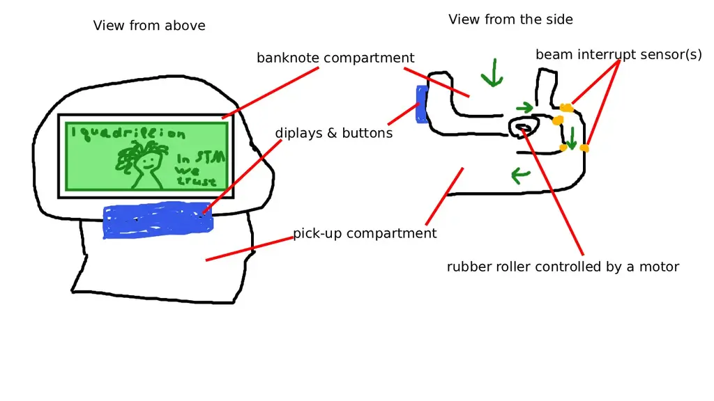
The user would place a stack of banknotes into the dedicated compartment. Then they would input the value of one banknote. After pressing the start button, the motor would pull the bottom banknote into a narrow slit, then, employing the gravity, the banknote would trigger the beam interrupt sensor, thus, increase the counter. If after a certain amount of time nothing triggers the sensor, the motor would stop. The front panel would feature the display, which would show the total sum along with the current value of one banknote; and a bunch of buttons, such as start, clear (set the counter and sum to 0), number inputs and preset banknote values (10/20/50/100 etc).
Log
Week 6
I have ordered all of the components, waiting for them to arrive.
Week 7
All of the components have arrived, and I decided to build an MVP prototype fully on breadboard, without the screen and actual pulling mechanism, just the logic.
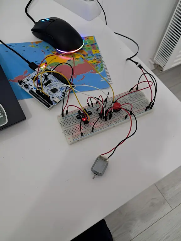
There were some issues, such as elecric noice generated by the spining motor interfering with the sensor signals. I had to add a capacitor and also filter the pulses in software, for now everything works fine.
So I've finished the coding part, added a bit of concurrency and it works as expected, now, I am ready move on to the most important part - the actual pulling mechanism.
Week 8
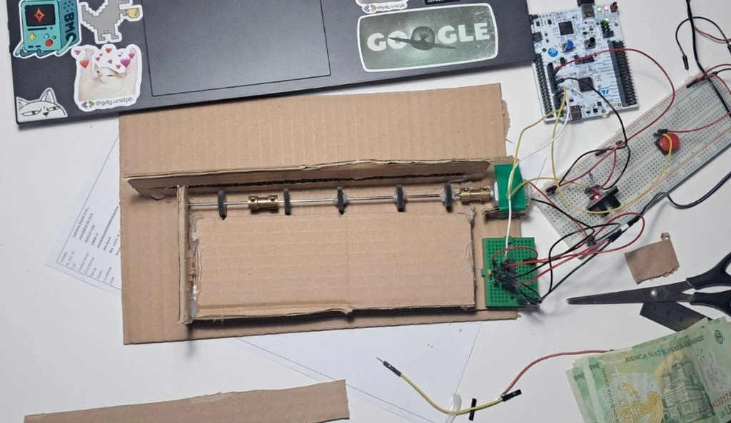
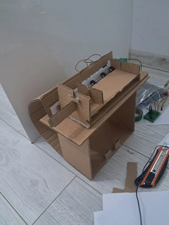
I started working on pulling mechanism, it works, but the extra pressure should be applied on the banknotes, and I haven't placed the sensor on the slit yet.
Week 9
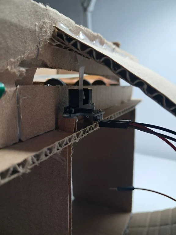
I've mounted the sensor into the structure:
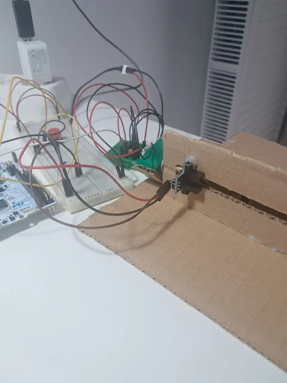
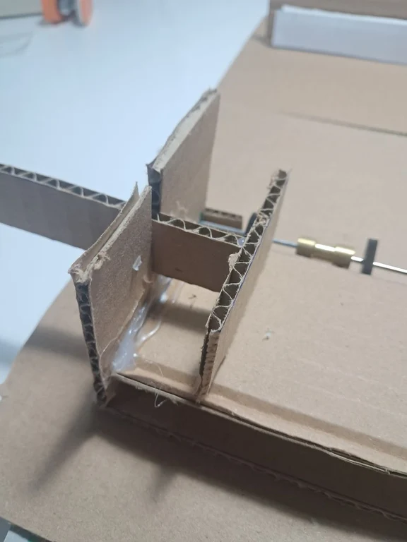
However I've run into the first physical limitation: the design of the sensor module does not allow me to place it in the middle of the banknote trajectory, only on the side. Since there are hundreds of currencies, thus, hundreds of banknote sizes, the issue arises: all of them need to be aligned so that their edge flies close to the one side. To achieve this, the stack should be pushed from the left towards the right wall, so I've added a little pushing mechanism and also glued up the "ramp":
Overall, the mechanical part turned out to be much more challenging than I expected, the biggest issue for now is multiple feed. I decided to temporary ignore it and move on to the rest of the peripherals.
This week I've also added the reset button and optimized the codebase.
Week 10
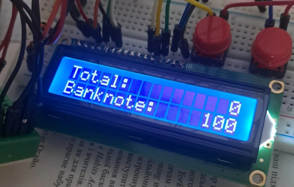
I tested an LCD and successfully integrated it into the project. It has a separate task that fetches the current value of the counter and updates the displayed value, if necessary.
Week 11
I've tested and integrated the 4x4 keypad into the system, now, the user may manually adjust the banknote value.
From the hardware point of view the project is all set, even though all of the components except the motor and the sensor are still on the breadboard. Before I mount them into the structure, I have to defeat the final boss of this project - the double feed. I've sacrificed the ruller in order to make the slit thinner, it reduced the double feed a lot, but now, the uniform external pressure has to be applied on the stack, and double banknotes still sneak into the slit from time to time.
Nevermind, forget it, the double feed is not the final boss, the final boss turned out to be... The Romanian Lei. It is made out of polymer that does not block the infrared light... It is totally on me that I noticed it only on week 11. The machine works fine with paper based currencies, I've tested it with EUR, USD, and UAH, but RON banknotes just fly through without any consecuences. I want this machine to be universal, so after hours of headache and research of how ATMs work, I came up with a decision to change the logic: the banknote does not trigger the sensor anymore, it is now triggered by a mechanical flag. I am going to move the sensor under the trajectory of the banknote, and attach a thin piece of paper to the ramp ceiling. In the idle state, that flag blocks the beam, and the passing banknote pushes it away so the beam appears.
From the software point of view, the logic is now reversed: we wait for rising edge, not for the falling one. With the new logic applied, due to motor vibration paper pendulum creates insane amount of false-triggers, so my next goal is to reconsider the pendulum material and position in order to minimize them. Increasing the debouncing interval may also resolve the issue.
Week 12
I've made the new pendulum out of PET plastic, it works great. However, the false triggers still occur because the new logic is applied. The motor generates a lot of electromagnetic noice and voltage spikes. I've already defeated the voltage spikes with a 100nF capacitor, but for the case EMI (elecromagnetic interference), I've just filtered the impulses in software, assuming that if the duration of a signal was less then 2ms it was coming from the motor, not from the sesor.
For the old falling-edge logic it worked fine: noice impulse -> EXTI falling edge -> sleep for 2ms -> check if the GPIO is still low, wich would immediately rise back to high after the noice is gone.
However, now, with a mechanical flag banknotes tend to jam or to get stuck in the slit from time to time, which keeps the sensor output high for a longer period of time. noice impulse -> EXTI rising edge -> sleep for 2ms -> check if the GPIO is still high, which is the case because the banknote is still there. Theoretically that issue could also occur with the old logic if the banknote got stuck in the slit, but on practice it only occured with the rising edges.
To address this, it would be better to physically reduce the noice rather than make some complex filtering algorithms. After some research I found out that communication cables utilize a twisted pair to fight the elecromagnetic radiation. So I twisted the motor<--->diriver wires and the sensor<--->breadboard wires, and it actually helped a lot.
I took a stack of 10 lei banknotes and decided that it is time for the first benchmark:
| # | Outuput |
|---|---|
| Expected value | 150 |
| 1 | 150 |
| 2 | 140 |
| 3 | 150 |
| 4 | 130 |
| 5 | 120 |
| 6 | 140 |
| 7 | 130 |
| 8 | 150 |
| 9 | 130 |
| 10 | 130 |
There are no cases where the outuput is greater then 150, meaning that false triggers do not occur anymore. Therefore I consider EMI to be defeated by now, and for the rest of the values, the error is coming from the double feed.
For the double feed, I glued up 3 sponges on the slit: 2 with insulating strip underneath for straightening the banknotes, and one with a toothpick sticked into it, acting as adjustable physical gate. After playing around with the toothpick and calibrating the debouncing configuration it works percise enough for now.
Week 13
I've finally mounted everything into the structure, and replaced external 830p breadboard with 3 small internal breadboards.
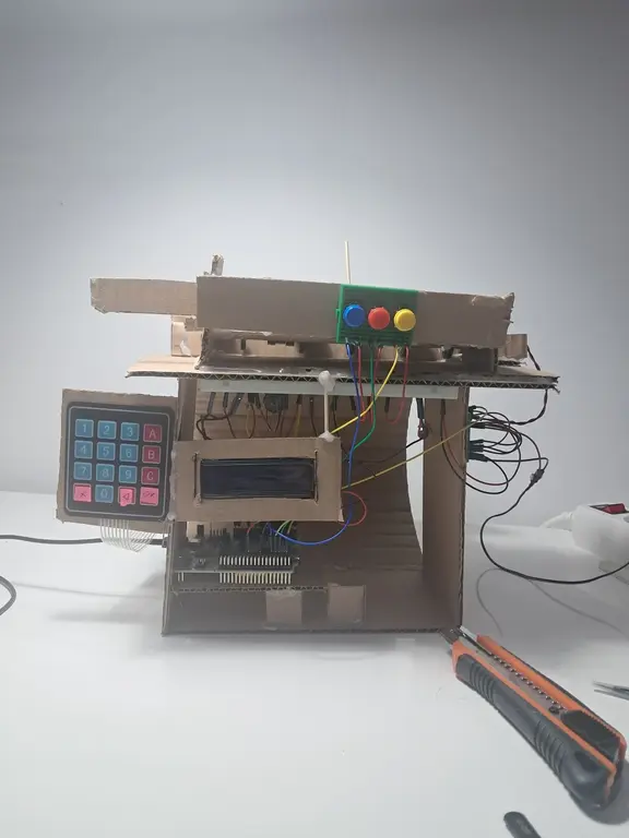
A few software tweaks, and thats it, the project is finished!
Hardware
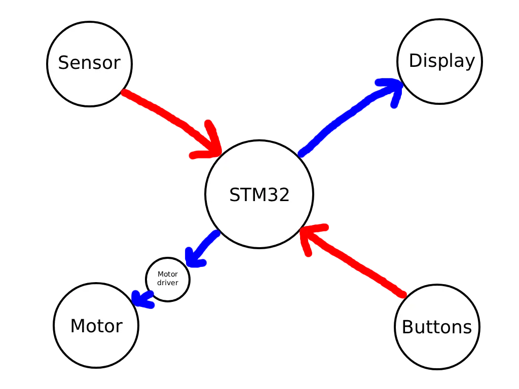
The "brain" of the system is STM32 microcontroller and the "eyes" of the system is IR beam interruption sensor.
The sensor has 3 terminals: Vcc, GND and OUT. OUT is high by default, and the sensor pulls it low only if there is something on the way of the beam (e.g. banknote)
Other main components are the LCD display, that is used as the information output; DC motor and driver, for pushing the banknote on the way of the sensor's beam; and the buttons and keypad for user interaction.
The initial plan was then the banknote would just fly through the sensor slit, however there was an issue with Romanian Lei banknotes: the polymer simply did not block the beam, so the sensor did not react to them at all. It worked fine with other currencies, but since I want this machine to be universal, I slightly changed the architecture: the banknote bumps into a piece of plastic, that moves a bit in the sensor slit and immediately returns to it's previous position. This creates a rising edge that gets handled by the STM.
Schematics

Bill of Materials
| Device | Usage | Qty | Price |
|---|---|---|---|
| STM32 Nucleo-U545RE-Q | The microcontroller | 1 | ~130 RON* |
| Mini Infrared Interruption Sensor Module | Detection of the passing banknote | 1 | 6.99 RON |
| 1602 LCD with Blue Backlight 3.3 V | The main display | 1 | 19.99 RON |
| DC Motor | Pulling the banknotes into the slit | 1 | 3.99 RON |
| L293D Motor Driver | The motor driver | 1 | 3 RON |
| 18 mm Rubber Wheel | The roller | 5 | 0.89 RON |
| 2x150 mm Shaft | The shaft for the roller | 1 | 1.95 RON |
| 2x50 mm Shaft | Shaft extention | 1 | 0.95 RON |
| 2 mm to 2 mm Coupling Hub | Shaft connections | 2 | 5.99 RON |
| Miniature Ball Bearing (2 mm Internal Diameter) | Shaft support | 1 | 2.89 RON |
| 4x4 Keypad | User input | 1 | 22.50 RON |
| Button with Round Cover | Start / Reset / Edit buttons | 3 | 1.99 RON |
| 10K Potentiometer | Adjusting the LCD contrast | 1 | 2.39 RON |
| Mini Breadboard | Wiring | 3 | 2.19 RON |
| Jumpers, Resistors, Capacitros etc | Basic electronics | - | ~20 RON |
| Cardboard | CAD (Cardboard Aided Design) | 1 | 4.40 RON |
| Total | ~250 RON |
*was borrowed from the lab
Software
| Library | Description | Usage |
|---|---|---|
| embassy-stm32 | Hardware Abstraction Layer for STM32 microcontrollers | Controlling GPIOs and extrenal interrupts (EXTIs) |
| embassy-sync | Synchronization primitives with async support | Mutexes and Watches for accessing the counter value |
| embassy-time | Instant and Duration for embedded no-std systems, with async timer support | Debouncing and other timers |
| embassy-executor | async/await executor | Spawning the processes |
| embassy-futures | Utilities for working with futures | Awaiting results from multiple processes |
| defmt | Logging framework for resource-constrained devices | Debug & Logging |
| defmt-rtt | defmt log messages over the RTT protocol | Debug & Logging |
| panic-probe | Panic handler that exits with an error code | Addressing errors |
| cortex-m | Low level access to Cortex-M processors | Embassy dependency |
| cortex-m-rt | Minimal runtime / startup for Cortex-M microcontrollers | Embassy dependency |
| hd44780-driver | Driver HD44780 compliant displays | Displaying the output |
| heapless | static friendly data structures that don't require dynamic memory allocation | Displaying strings on the LCD properly |