BytArm
A compact embedded robotic arm system powered by an STM32 microcontroller, capable of real-time control of multiple servo motors using analog inputs, designed to explore low-level hardware interaction and precise motion control.
Author: Tomulescu Eduard Gabriel
GitHub Project Link: https://github.com/UPB-PMRust-Students/fils-project-2026-Edward11-boop
Description
This project focuses on building an embedded robotic arm control system using the STM32F446RE microcontroller and the Rust programming language. The goal is to control multiple servo motors in real time using analog inputs from potentiometers.
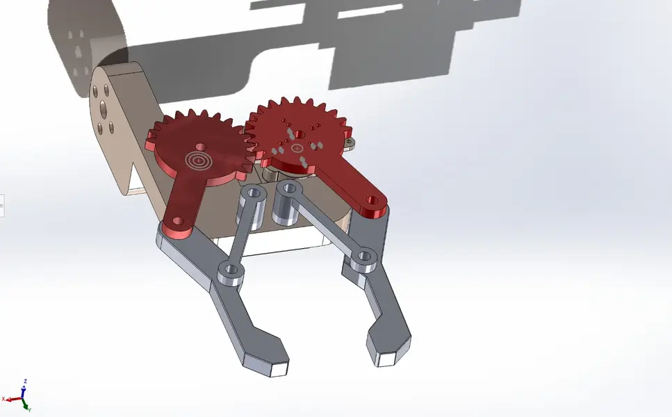
The robotic arm has four degrees of freedom: base rotation, shoulder, elbow, and a claw mechanism. Each of these is controlled independently through a dedicated potentiometer, allowing smooth and continuous motion.
The system relies on PWM signals generated by the STM32 timers to control the servo motors, while analog values are read using the ADC. The firmware is written in Rust using the Embassy framework, which allows asynchronous and non-blocking execution.
Motivation
I chose this project because I wanted to better understand how hardware and software interact in an embedded system. Working with a robotic arm allows me to see directly how code translates into physical movement.
At the same time, I wanted to explore Rust in an embedded context and understand how asynchronous programming works on microcontrollers. This project helps me build both practical hardware experience and deeper low-level programming knowledge.
Architecture
The system is built around a simple control loop that continuously reads analog input values and converts them into servo motor positions.
Each potentiometer controls one servo motor, corresponding to a joint of the robotic arm. The STM32 microcontroller reads analog values using the ADC and generates PWM signals using hardware timers.
The system is structured in a modular way so that each component, input reading, signal processing, and output control, can be extended or improved independently.
Main components of the system:
- Input subsystem, responsible for reading analog values from potentiometers
- Processing subsystem, which maps input values to servo angles
- Output subsystem, responsible for generating PWM signals for servo control
Log
Week 3
In this week, I spent some time thinking about what kind of project I would like to build and what I could learn from it. After looking at a few options, I decided to go with a robotic arm control system because it combines both hardware and software in an interesting way. I also considered the difficulty of the project and whether it would allow me to learn something new without being too overwhelming.
I also started looking into what technologies I might use and discovered the Embassy framework, which seemed like a good opportunity to explore asynchronous programming in an embedded environment.
Week 4
After deciding on the idea, I started learning more about the components involved. I looked into how servo motors work and how they are controlled using PWM signals. I also studied how potentiometers can be used as inputs and how their analog values are read by a microcontroller.
During this week, I also tried to better understand how all these components would interact together and started forming a clearer image of how the system should be structured.
Week 5
During this week, I focused on understanding the STM32F446RE microcontroller and how I can use its ADC and timers for this project. I read documentation and examples to understand how to configure peripherals and how to generate PWM signals.
I also finalized the list of components needed for the project and made sure that everything I planned to use would be compatible and realistic to implement.
Week 6 - 7
In these weeks, I set up the development environment and started working with the Embassy framework. This part took some time because I had to get used to the toolchain and understand how async tasks work in embedded Rust.
Instead of trying to build the whole system at once, I focused on small tests. I experimented with reading values from a potentiometer and then used those values to control a single servo motor. This helped me understand how the input-output mapping works in practice.
I also encountered small issues related to timing and signal stability, which helped me better understand how precise control needs to be when working with hardware.
Week 8
At this stage, I am working on designing the actual structure of the robotic arm and thinking about how all the components will fit together. I am focusing on the physical layout and how each servo should be positioned for a stable and functional design.
I am also trying to balance both the mechanical and software parts of the project, since the final result depends on how well these two aspects integrate. At the same time, I continue testing multiple servo control to ensure the system behaves consistently.
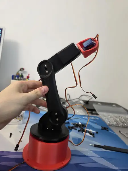
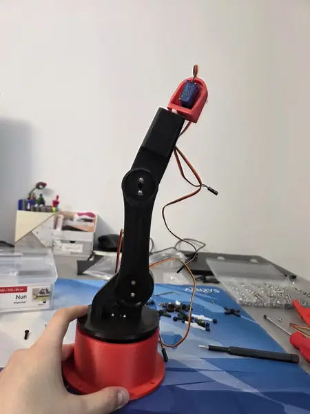
Hardware
The hardware setup includes an STM32 microcontroller, multiple servo motors, potentiometers, and basic prototyping components such as a breadboard and jumper wires.
Photos
Schematics

Bill of Materials
| Device | Usage | Price |
|---|---|---|
| STM32F446RE (Nucleo Board) | Main microcontroller | 150 RON |
| SG90 Servo Motor | Controls each joint | 13.99 RON |
| Potentiometer (10kΩ) | Analog input | 1 RON |
| Breadboard | Prototyping | 5 RON |
| Jumper wires | Connections | 8 RON |
| 9V Battery (6LR61) | Powers the system | 10 RON |
| Capacitor 470µF | Stabilization | 0.50 RON |
Software
| Library | Description | Usage |
|---|---|---|
| embassy-stm32 | Hardware abstraction layer | Used to control STM32 peripherals |
| embassy-executor | Async task executor | Runs asynchronous tasks |
| embassy-time | Timing and delays | Used for timing |
| embassy-sync | Synchronization primitives | Manages shared resources |
| cortex-m | CPU access | Low-level processor access |
| cortex-m-rt | Runtime support | Handles startup |
| defmt | Logging | Debugging |
| defmt-rtt | Debug output | Outputs logs |
| panic-probe | Panic handler | Handles errors |