Environment-monitor
A connected weather station powered by the Raspberry Pi Pico 2 W, featuring local SD card recording, an active LCD dashboard, and wireless synchronization for long-range data tracking.
Author: Mykyta Troinych
GitHub Project Link: https://github.com/UPB-PMRust-Students/fils-project-2026-TrOyKa23
Description
Environment-monitor runs as an asynchronous Rust program on the RP2350 microcontroller inside the Raspberry Pi Pico 2 W. It regularly polls ambient air pressure and temperature via a BME280 unit connected through an I2C bus, renders live sparklines and stats onto an ST7789 display, appends telemetry to a MicroSD card (TEMPLOG.CSV), and uploads batched records over the network every half-hour to an external host for comprehensive trend analysis.
Motivation
The initiative was undertaken for self-education and exploration into Rust-based embedded engineering, asynchronous hardware schedulers like Embassy, multiplexing a shared SPI bus, handling micro-scale filesystems, and working with IoT networking stacks.
Architecture
Concurrent tasks are managed on the RP2350 chip using an async Rust environment:
- Central Controller: Raspberry Pi Pico 2 W executing the Embassy task runner.
- BME280 Sensor: Links via I2C0 to capture pressure and temperature metrics.
- Display and Storage: The ST7789 screen and SD card share the SPI1 channel, controlled via synchronized SPI device wrappers (
SpiDeviceWithConfig). - Debugging Probe: A separate Raspberry Pi Pico 2 W provides out-of-circuit debugging over SWD (SWCLK and SWDIO lines).
- Wireless Layer: Relies on the
cyw43andembassy-netlibraries for TCP/IP communications.
                      +-------------------------+           +-------------------------+
                      |            CORE         |           |            DEBUG        |
                      |   Raspberry Pi Pico 2 W |-----------|   Raspberry Pi Pico 2 W |
                      |        (RP2350)         |           |        (RP2350)         |
                      +------------+------------+           +------------+------------+
                                   |
         +-------------------------+-------------------------+
         | I2C0                    | SPI1 (Shared Bus)       | CYW43439 (Wi-Fi)
         v                         |                         v
+------------------+     +---------+---------+      +------------------+
| BME280 Sensor    |     |                   |      | Server / Web App |
| Temp & Pressure  |     v                   v      | (Trend Graphs)   |
+------------------+ +-------+           +-------+  +------------------+
                     | ST7789|           | SD    |
                     | LCD   |           | Card  |
                     +-------+           +-------+
Log
Milestone 1 — Project Initialization & Sensor Setup
- Configured the toolchain for
thumbv8m.main-none-eabihfalongside RP2350-specific configurations (memory.xandbuild.rs). - Integrated the
bme280-rslibrary for asynchronous I2C communication. - Enabled RTT diagnostics utilizing
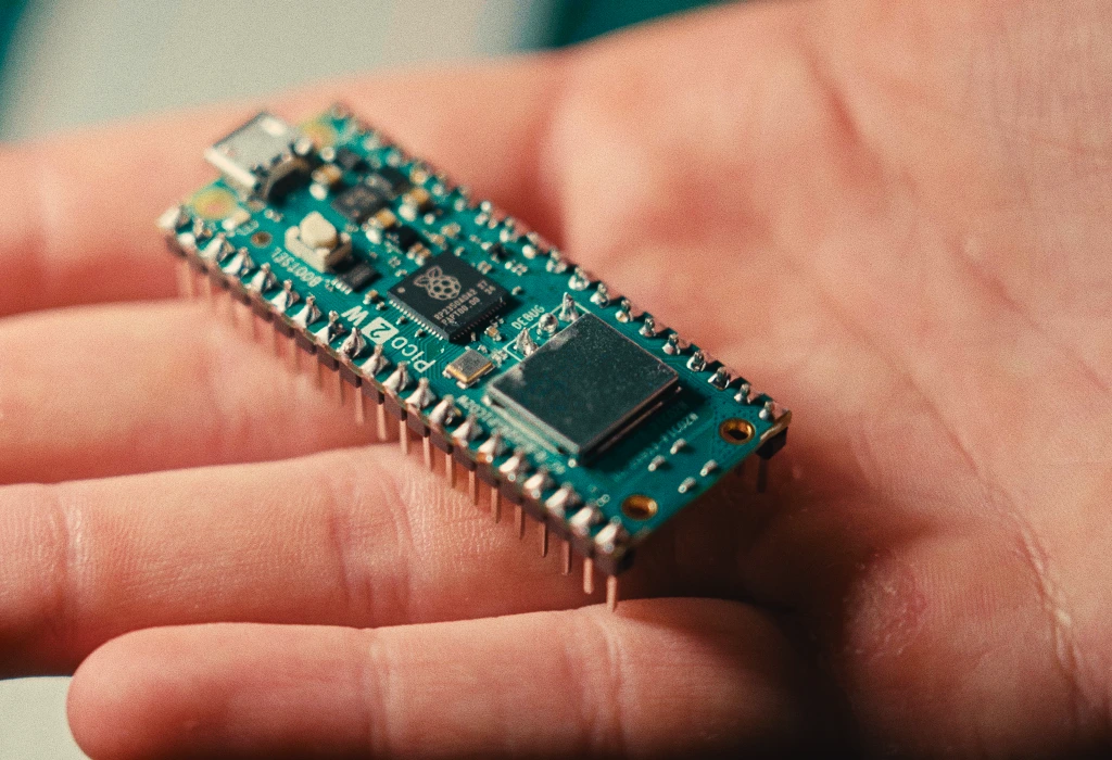
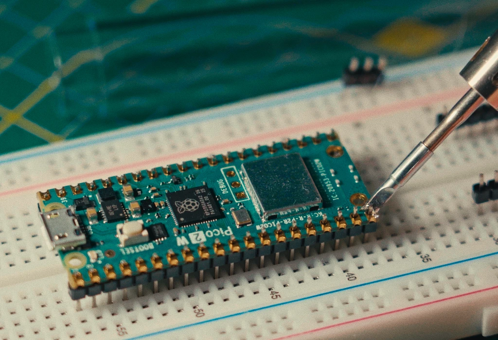
defmt-rttcombined withpanic-probe. - Soldered physical connections on both the Pico 2 W board and the BME280 breakout.
Milestone 2 — Shared SPI Bus & Display UI
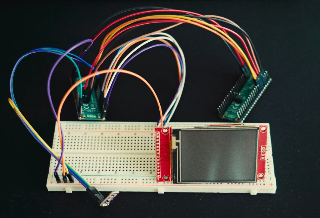
- Hooked up the ST7789 screen using the
mipidsicrate over the SPI1 interface. - Developed
ui.rsto generate a graphical interface complete with a top status bar, active icons, running uptime counters, large digit displays, and miniature historical charts built withembedded-graphics.
Milestone 3 — SD Card Filesystem Integration
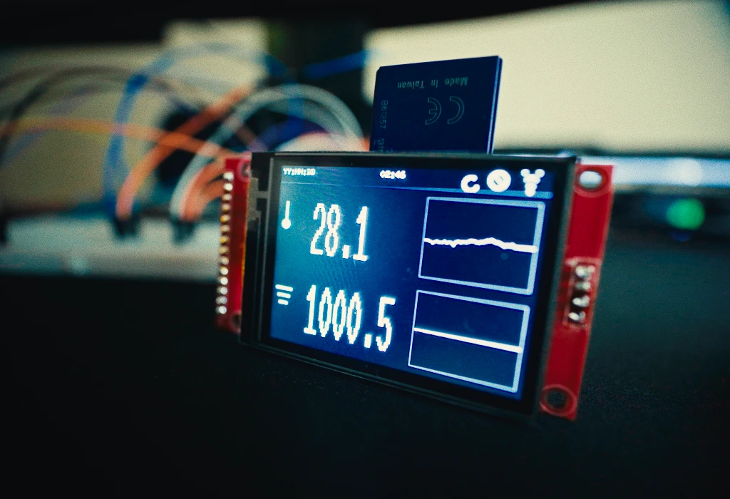
- Established a shared bus layout (
SpiDeviceWithConfigtogether withNoopRawMutex) to cleanly share the SPI channel between the display and storage module. - Employed
embedded-sdmmcto handle FAT filesystems and automate writing comma-separated log entries intoTEMPLOG.CSVwith proper column headers. - Synchronizing display output and storage updates.
Milestone 4 — Async Network Stack & Server Sync
- Initialized the
cyw43-piodriver and necessary background routines for the CYW43439 Wi-Fi chip. - Set up a 30-minute interval trigger to bundle recorded logs and transmit them via HTTP/TCP to an upstream server for graphical rendering.
Milestone 5 — NTP Time Sync & Robust SD Logging
- Configured a background wireless service to connect through DHCP and fetch accurate UTC timestamps from an NTP server upon startup.
- Introduced a lightweight software RTC (
rtc.rs) that calculates current dates and times based on the NTP anchor plus elapsed system uptime, adjusted for local timezone offsets. - CSV entries now feature precise Date and Time fields (replacing raw uptime tallies) alongside pressure and temperature readings; writing is deferred until time synchronization completes to maintain uniform records from the start.
- The UI header switches from a placeholder to the synchronized clock once network time is acquired.
- Added hot-plug recovery for the MicroSD card: extracting and reinserting the card allows file operations to resume automatically without requiring a hard reset.
Milestone 6 - 3D Print
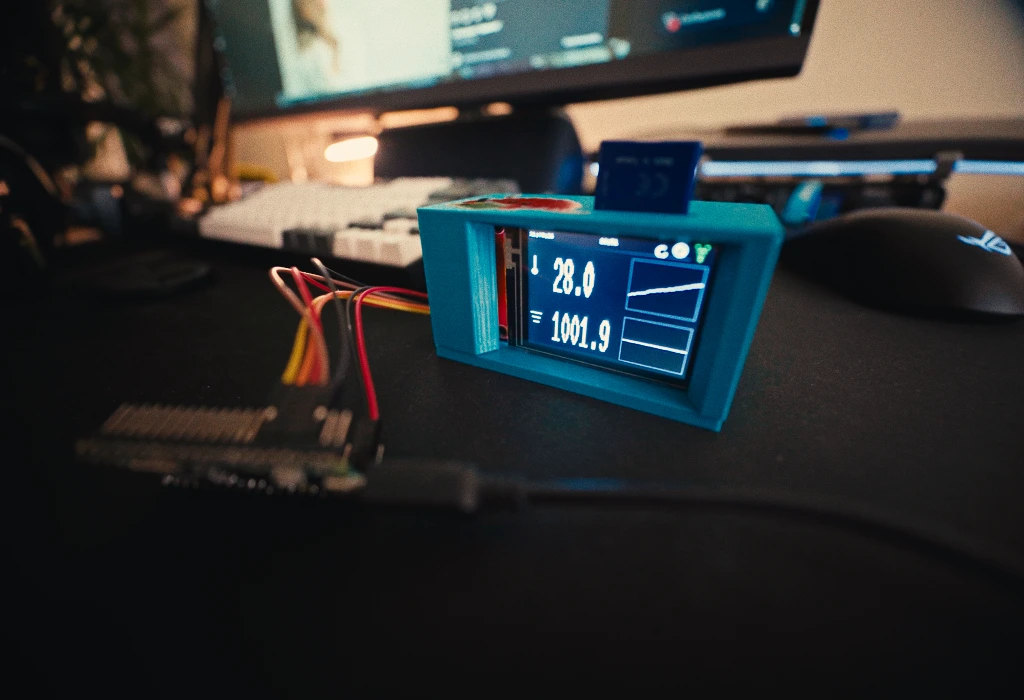
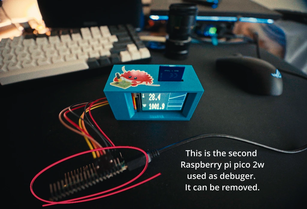
The custom enclosure for this project was designed from scratch using Blender. Since the primary focus of this initiative is learning embedded programming, asynchronous Rust, and networking, the current iteration of the case is a functional prototype. It is slightly flimsy and requires minor dimensional adjustments for a perfect fit, but it serves its purpose perfectly well for housing the components on a desk.
-
Design Challenges in Blender: Designing a functional electronic case in a polygonal modeling tool like Blender (rather than a parametric CAD tool) presented several specific challenges:
-
Wall Thickness & Rigidity: Finding the right balance for wall thickness was tricky. The current walls are a bit too thin (leading to the flimsy feel), and adding structural ribs or using the
Solidifymodifier without creating overlapping geometry required manual cleanup. -
Component Tolerances: Fitting exact real-world dimensions for the Raspberry Pi Pico 2 W, the 2.4" ST7789 display, and the BME280 sensor required tight tolerances. Leaving exact cutouts for the Micro-USB cable and the MicroSD card slot often required manual vertex pushing, as Blender lacks parametric history.
-
Manifold Geometry: Ensuring the final mesh was completely watertight (manifold) for the slicer software without any flipped normals or internal faces.
-
Mounting Points: Designing internal standoffs and snap-fits for the components that are both printable without extensive supports and strong enough not to break off during assembly.
Hardware
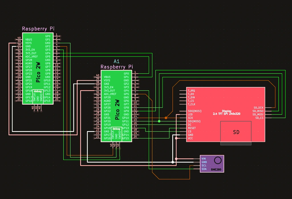
The system utilizes a Raspberry Pi Pico 2 W as the central unit connected to an environmental sensor, a color TFT display, and an integrated MicroSD card module.
Schematics
Bill of Materials
| Device | Usage | Price |
|---|---|---|
| Raspberry Pi Pico 2 W | Core Microcontroller (RP2350) + Wi-Fi | 60 RON |
| Raspberry Pi Pico 2 W | Secondary Pico used as SWD Debugger Probe | 60 RON |
| BME280 Sensor Module | Temperature and Pressure sensor (I2C) | 22 RON |
| ST7789 2.4" TFT LCD Module with SD Slot | 240x320 Display + SD Card Reader (SPI) | 50 RON |
Software
| Library | Description | Usage |
|---|---|---|
| embassy-executor | Async task executor | Drives background execution tasks |
| embassy-rp | RP2350 Hardware Abstraction Layer | Manages I2C, SPI, GPIO, PIO, and hardware peripherals |
| bme280-rs | Async BME280 sensor driver | Reads temperature and pressure data asynchronously |
| mipidsi | Display controller driver | Drives ST7789 LCD display initialization |
| embedded-graphics | 2D graphics engine | Renders text, icons, containers, and sparkline trend graphs |
| embedded-sdmmc | FAT volume and SD card driver | Writes CSV log records to SD filesystem |
| cyw43 | Wi-Fi chip driver | Manages wireless connection on CYW43439 |
| embassy-net | Async network stack | Handles DHCP, TCP, and network sockets |
| defmt | Efficient logging framework | Prints internal diagnostics and status over SWD/RTT |