Braille Bidirectional Trainer
An interactive system for learning Braille through visual, tactile and auditory feedback.
Author: Ciuperca Robert-Mihai
GitHub Project Link: Project Repository
Description
The Braille Bidirectional Trainer is a dual-mode educational device. Mode 1 teaches sighted users to write Braille using a 3×3 button matrix, where the second and third columns function as a Braille-style 3×2 input interface based on prompts displayed on the screen. Mode 2 helps visually impaired users practice reading through a 6-solenoid tactile display, with responses entered using the full 3×3 matrix configured as a T9-style keypad and validated through audio feedback.
Motivation
I chose this project after meeting a visually impaired person and realizing how much a basic knowledge of Braille would have helped our communication. This experience inspired me to create a tool that assists parents and teachers in supporting blind children, while providing young learners with an interactive, fun way to practice their tactile skills.
Architecture

The system operates in two modes, selected at startup by pressing specific buttons. Each mode has 3 levels of increasing difficulty, and the user must achieve at least 80% accuracy to advance.
Mode 1 — Learn to Write Braille (Sighted Users)
The OLED display shows a random letter or word. The user encodes it in Braille using the second and third columns of the 3×3 button matrix, which together emulate a standard 3×2 Braille cell. There is no confirmation button; instead, the system waits approximately two seconds for the user to press the buttons they consider to represent the correct Braille character, after which the answer is automatically validated. A green LED lights up for correct answers, while a red LED indicates an incorrect response.
Mode 2 — Learn to Read Braille (Blind Users)
The STM32 activates solenoids through an 8-channel relay module to physically raise Braille dots on a tactile plate. The user feels the pattern and types the corresponding letter on 9 red buttons arranged as a phone keypad (multi-press input, like old Nokia phones). Feedback is given via buzzer: one beep for correct, two beeps for incorrect. The STM32 NUCLEO-U545RE-Q acts as the central controller, managing all input/output:
- Input: 9 red buttons (GPIO)
- Display: 0.91" OLED 128×32 via I2C — shows letters, words and game status
- Tactile output: 6 push-pull solenoids (5V 0.7A) driven by an 8-channel relay module
- Feedback: Bicolor LED (Mode 1) and passive buzzer via PWM (Mode 2)
- Power: USB-C for STM32, separate 5V 6A PSU for solenoids
Log
Week 20 - 26 April
- Drafted the initial hardware documentation (block structure, component list, wiring notes)
- Ordered all required components from Optimus Digital, eMAG, Farnell, AliExpress and Ground Studio
- Refined the project concept: defined the two operating modes (sighted / blind), the level progression logic, and how the selection screen switches between them
Week 27 April - 3 May
- The majority of the hardware components arrived
- Began learning how to connect and integrate the electronic components
- Studied the datasheets for the STM32, OLED display, relay module, and solenoids
Week 4 - 10 May
- Attended the Support Project Work session
- Received guidance and recommendations from the assistants regarding the hardware implementation
Week 11 - 17 May
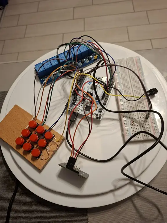
- Built the hardware part of the project
- Connected and tested the main electronic components
- Assembled the keypad matrix
Week 18 - 24 May
Hardware
1. STM32 Nucleo-U545RE-Q - Main Microcontroller Unit
- Handles: buttons (GPIO), OLED (I2C), LEDs (GPIO), buzzer (PWM)
2. 6 Mini Push-Pull Solenoids (5V, 0.7A)
- Tactile Braille output: 3×2 dot matrix under the tactile plate
- Powered from external 5V/6A supply switched by the relay module
3. 0.91" OLED Display (128×32, I2C)
- Visual output for Mode 1: displays random letters, short words and complex words that the user must encode in Braille
4. Push Buttons (16 total)
- 9 red buttons form a Nokia T9 keypad (3x3)
- All buttons are debounced in software
5. Relay Driver Stage (8-Channel Optoisolated Relay Module)
- One relay channel per solenoid (6 out of 8 channels used; channels 7 and 8 unused)
- Low-side switching for solenoids via relay contacts
- Jumper between VCC and JD-VCC must be removed when external PSU is connected (failure to do so risks damaging STM32 and laptop USB port)
- No external flyback diodes, gate resistors or pull-downs required (all handled internally by the relay module)
6. Feedback Outputs
- 1 Bicolor LED (green/red - correct/wrong) working via 220Ω resistor
- 1 passive buzzer for Mode 2 (1 beep = correct, 2 beeps = wrong)
7. Power Subsystem
- External 5V/6A feeds the solenoids only: solenoids use up to ~4.2A peak (6 * 0.7A)
- MCU powered via USB-C, only GND shared between the two supplies
8. Passives & Wiring
- Resistors: 220Ω (LED, MOSFET gates), 10kΩ (pull-downs), 1kΩ (buzzer transistor base)
- 1× breadboard 830pt
- M-M, M-F, F-F jumpers; plexiglass tactile plate with 6 holes for solenoid pistons
9. Physical Assembly
- Plexiglass tactile plate with 6 holes drilled for solenoid pistons
- Solenoids mounted underneath, aligned with the holes
- Buttons arranged on top (T9 keypad)
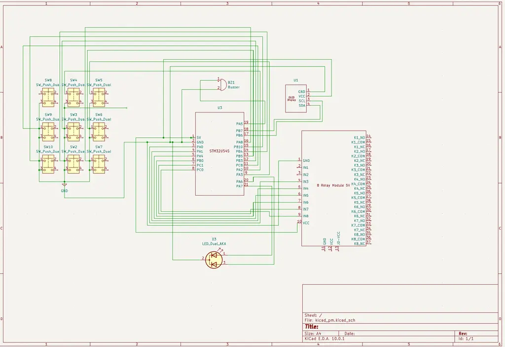
Schematics
Bill of Materials
| Device | Usage | Price |
|---|---|---|
| STM32 Nucleo-U545RE-Q | Main microcontroller | 130 RON |
| Mini Push-Pull Solenoids | Raises/Lowers Braille dots | 130 RON |
| OLED Display | Displays letters/words | 38 RON |
| 9 red buttons | Nokita T9 keypad (3x3 matrix) | 18 RON |
| Bicolor LED | Visual feedback | 1 RON |
| 5V6A Power Supply | Powers solenoids | 52 RON |
| 8 Relay Module | Controls solenoids activation | 26 RON |
| Breadboard | Connects all electronic parts | 10 RON |
| Buzzer | Audio feedback | 1 RON |
| Resistors, capacitors, diodes, wires | Support the main components | ~30 RON |
| Perforated board | Solenoids mounted underneath raise through the holes | ~10RON |
Software
| Library | Description | Usage |
|---|---|---|
| embassy-stm32 | Hardware Interface | Acts as a bridge between the Rust code and the physical pins (GPIO, I2C, PWM) |
| defmt | Debug Logging | Sends status messages to the computer for debugging via probe |
| panic-probe | Error Handling | Reports crashes and errors through the debug probe |
The rest will be added as I develop the code