AutoNav
Autonomous Robot with Mapping and Simplified SLAM
Author: Anca Stefania Maxim
GitHub Project Link: https://github.com/UPB-PMRust-Students/acs-project-2026-ancamaxim
Description
AutoNav is an autonomous mobile robot that explores an unknown space, builds a 2D obstacle map in real time, and makes navigation decisions independently — without human intervention. The project implements a simplified SLAM (Simultaneous Localization and Mapping) system, adapted to the hardware constraints of an STM32 microcontroller.
The robot uses three ultrasonic sensors and a scanning servo to detect surrounding obstacles, wheel encoders for odometry, and an IMU for heading error correction. From this data, it builds a probabilistic occupancy grid — a 2D map where each cell has an associated probability of containing an obstacle.
The map is displayed live on a color LCD mounted on the robot, updated at 10Hz. Simultaneously, data is transmitted wirelessly via ESP8266 to a PC, where it can be visualized in real time through a graphical interface.
The exploration algorithm uses frontier-based exploration: the robot identifies boundaries between explored and unknown space and autonomously heads toward the nearest unexplored frontier until the accessible space is completely mapped.
Motivation
This project was chosen because it covers all peripherals and protocols studied in the lab — SPI, I2C, UART, PWM, GPIO, ADC, TIM input capture — demonstrated simultaneously in a functional integrated system. It implements algorithms relevant to real-world applications: odometry, sensor fusion, probabilistic mapping, and graph search for trajectory planning — all in Rust without an operating system. Similar SLAM systems are used in industrial robots (Amazon warehouses), autonomous vacuum cleaners (Roomba), exploration drones, and autonomous vehicles.
Architecture
The system is structured in four functional layers:
- Perception Layer: 3x HC-SR04 + scanning servo + MPU-6050 IMU + wheel encoders — collects data about the environment and robot movement
- Localization Layer: odometry from encoders, fused with the IMU gyroscope through a complementary filter — estimates the robot's position and orientation in space
- Mapping Layer: 32x32 occupancy grid updated through Bresenham ray casting — builds the probabilistic obstacle map
- Planning Layer: frontier-based exploration + PID on heading — decides the next destination and controls movement

Processing Pipeline
At each 100ms cycle, the system executes sequentially:
- Read encoders -> calculate distance traveled per wheel
- Read IMU gyroscope -> heading correction through complementary filter
- Update odometry -> current position (x, y, theta) in space
- Servo scan 5 positions -> 5 ultrasonic distances -> 5 obstacle points in space
- Update occupancy grid -> ray casting for free cells + obstacle probability increment
- Frontier detection -> find nearest unexplored cell adjacent to free space
- PID heading -> direction correction calculation -> motor PWM
- LCD render -> updated 2D map + robot position + status
- UART ESP8266 -> compressed grid wireless transmission
Log
Week 5 - 11 May
Decided upon hardware components and designed a block scheme with the hardware architecture I will built.
Week 12 - 18 May
Asembled hardware components, tested each component (to verify its functionality) through simple tasks and finalized hardware implementation.
Week 19 - 25 May
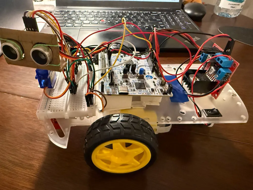
Hardware
The robot is built on a 2WD chassis with two DC motors with Hall encoders for precise odometry. Three HC-SR04 ultrasonic sensors (front, left, right) mounted on an SG90 scanning servo provide obstacle detection. An MPU-6050 IMU handles heading correction, while two IR sensors detect floor edges. An ST7735 128x160 color LCD displays the live map, and an ESP8266 WiFi module streams data wirelessly to a PC. The system is powered by a 7.4V 2000mAh LiPo battery with an LM2596 voltage regulator.
Schematics

Bill of Materials
| Device | Usage | Price |
|---|---|---|
| STM32 Nucleo-U545RE-Q | Main microcontroller | provided |
| 2WD Robot Chassis | Physical robot structure | 30 RON |
| DC Motors with Hall Encoders x2 | Propulsion + precise odometry | 40 RON |
| L298N Motor Driver | Dual H-bridge motor control | 15 RON |
| HC-SR04 Ultrasonic Sensor x3 | Distance measurement front + left + right | 20 RON |
| SG90 Servo Motor | Front sensor 180° rotation scanning | 15 RON |
| MPU-6050 IMU | Gyroscope heading + accelerometer | 15 RON |
| IR Sensors x2 | Floor edge / table edge detection | 10 RON |
| ST7735 LCD 128x160 | Live 2D map + robot status display | 20 RON |
| ESP8266 WiFi Module | Wireless map streaming to PC | 20 RON |
| RGB LEDs x4 | Visual robot state status | 8 RON |
| Passive Buzzer | Audio feedback for events | 5 RON |
| LiPo Battery 7.4V 2000mAh | Autonomous power supply (~45min) | 35 RON |
| LM2596 5V Regulator | Voltage step-down for logic | 10 RON |
| Capacitors 100uF x4 | Motor noise filtering | 5 RON |
| Breadboard + Jumper Wires | Prototype circuit | 30 RON |
| Resistors + Misc | Protection + connections | 8 RON |
Software
| Library | Description | Usage |
|---|---|---|
| embassy-stm32 | Async HAL for STM32 | Used as the main async runtime and hardware abstraction layer for STM32U5 |
| embassy-executor | Async executor without OS | Used for concurrent task scheduling (sensor, odometry, SLAM, display, WiFi tasks) |
| embassy-time | Precision timers | Used for microsecond-precision timing for sensor readings and task scheduling |
| embedded-graphics | 2D graphics library | Used for rendering the 2D occupancy grid map on the LCD |
| st7735-lcd | Display driver for ST7735 | Used to drive the ST7735 128x160 color LCD via SPI |
| heapless | Static data structures | Used for Vec and Queue without heap allocation |
| libm | Math functions in no_std | Used for sin, cos, sqrt calculations in odometry and SLAM |