IoT Weather-Station: Meteo and Air Quality Monitor
A smart IoT station for monitoring weather and air quality, featuring acoustic alerts and a live cloud dashboard.
Author: Mitran Ramona Luminița
GitHub Project Link: UPB-PMRust-Students/acs-project-2026-mnoramona
Description
This project consists of an IoT station capable of measuring environmental parameters and displaying them in real-time on an online dashboard (Adafruit IO). The system reads temperature and atmospheric pressure (via I2C), measures UV ray intensity (via ADC), and monitors air quality by detecting CO2, ammonia, benzene, and smoke using an MQ-135 sensor. When safety thresholds are exceeded, a buzzer triggers distinct acoustic alarms depending on the specific hazard.
Additionally, two physical push-buttons are integrated into the system using software debouncing algorithms (polling). The primary button features dual functionality: a short press toggles a continuous data upload mode (every 15 seconds), while a long press (3 seconds) calibrates the gas sensor by setting a new clean-air reference zero. The second button acts as a "Mute/Snooze" switch, silencing the acoustic alarms for 1 minute if the user acknowledges the hazard.
Motivation
I chose this project because it offers a highly practical and relevant application (environmental health monitoring) while elegantly integrating multiple fundamental concepts of electronics and embedded programming. The project natively covers a wide range of hardware communication protocols - I2C for digital sensors, ADC for analog signals, and software polling (debouncing) for asynchronous events - and bridges the gap to the Internet of Things (IoT) by transmitting data over Wi-Fi via the MQTT protocol.
Architecture
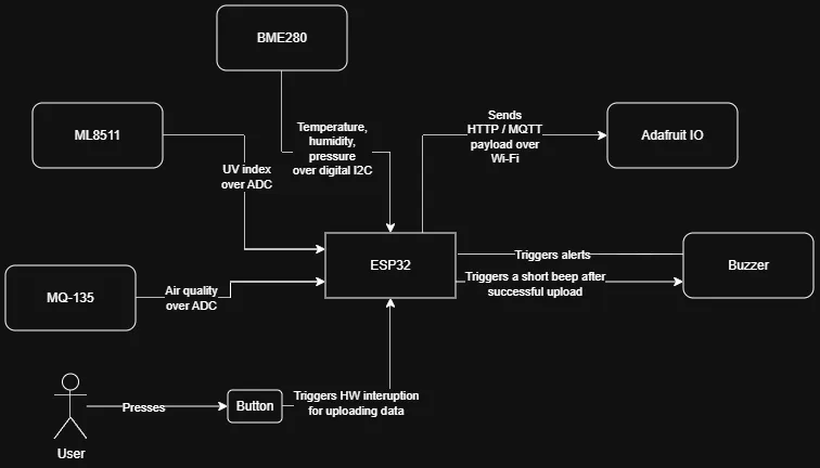
The system is built around a central microcontroller that interfaces with various input and output modules:
- Processing Unit (ESP32): Reads sensor data, applies digital filters and business logic (mapping ADC voltages for the UV and MQ-135 sensors), and manages the Wi-Fi connection.
- Digital Input Module (I2C): The BME280 sensor communicates bidirectionally over the I2C bus (SDA/SCL) to provide precise temperature, humidity, and pressure data.
- Analog Input Module (ADC): The ML8511 (UV) and MQ-135 (Air Quality) sensors output a variable voltage that is read by the ESP32's ADC pins.
- Digital Input Module (Buttons & Polling): Two push-buttons are connected to digital pins with internal pull-up resistors. The system uses a non-blocking polling method (millis()):
- Button 1: Short press toggles continuous 15-second data upload; Long press (3s) calibrates the MQ-135 zero baseline.
- Button 2: Triggers a 1-minute alarm snooze.
- Local Output Module: A buzzer provides immediate acoustic feedback, generating specific patterns:
- Gas Alarm (Siren): Continuous long beeps when dangerous gas levels are detected (MQ-135 raw > 1000).
- Temperature Alarm: 3 rapid, sharp beeps when ambient temperature exceeds 28°C.
- Status Beep: Short beeps for upload toggle confirmation, and a rapid burst pattern for successful gas sensor calibration.
- Cloud Module: Adafruit IO receives JSON/MQTT payloads and visualizes the data on live charts.
Log
Week 27 April - 3 May
- Created documentation and bill of materials.
Week 4 - 10 May
- Wired and tested the I2C (BME280) and ADC (MQ-135, ML8511) sensors.
- Calibrated the ADC mapping for the UV sensor to calculate the UV Index.
Week 11 - 17 May
- Configured Adafruit IO feeds and implemented the Wi-Fi & MQTT connection.
- Added the buzzer and dual-button logic. Replaced hardware interrupts with a
millis()-based debounce polling architecture for stability. - Implemented distinct buzzer alarm patterns and the 5-minute snooze logic.
Week 18 - 24 May
- Finalized code logic, cleaned up the project structure, and completed the final testing.
Week 25 - 27 May
- Implemented short/long press logic for continuous MQTT upload toggling and real-time MQ-135 gas sensor zeroing.
- Added 1-minute snooze functionality and aggressive buzzer patterns for noisy environments.
Hardware
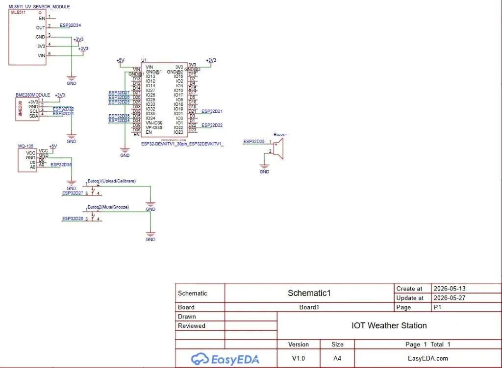
The project utilizes an ESP32 microcontroller due to its native Wi-Fi capabilities and generous pinout. The selected sensors cover both digital communication (BME280) and analog voltage reading (ML8511 and MQ-135). Two push-buttons serve as input triggers for cloud uploads and alarms, and a buzzer adds a layer of local user interaction.
Schematics
Bill of Materials
| Device | Usage | Price |
|---|---|---|
| ESP32 DevKit V1 | Main microcontroller for processing and Wi-Fi connectivity. | 30 RON |
| BME280 Sensor Module | Measures temperature, humidity, and atmospheric pressure (I2C). | 34 RON |
| ML8511 UV Sensor | Detects ultraviolet light intensity (ADC). | 33 RON |
| MQ-135 Air Quality Sensor | Detects gas levels (CO2, ammonia, benzene, smoke) (ADC/Digital). | 22 RON |
| 5V Passive/Active Buzzer | Acoustic warning module for exceeded safety thresholds. | 2 RON |
| 2x Push-Buttons | One for forcing MQTT data upload, one for the 5-minute Alarm Snooze/Mute feature. | 4 RON |
| Breadboard & Jumper Wires | For rapid prototyping and circuit connections. | 20 RON |
Software
| Library | Description | Usage |
|---|---|---|
WiFi.h | Standard ESP32 library for wireless networking. | Used to connect the microcontroller to the local internet router. |
Adafruit MQTT Library | Robust MQTT client for Arduino/ESP. | Used to package and transmit data to the Adafruit IO dashboard. |
Wire.h | I2C communication library. | Used to initiate and read data from the I2C bus (SDA/SCL pins). |
Adafruit_BME280 | Software driver for the BME280 sensor. | Used to extract temperature, humidity, and pressure data. |