Runaway Alarm Clock
An autonomous runaway alarm clock that uses proximity sensors to detect the user and physically escape via motorized movement.
Author: Alin Andrei Abahnencei
GitHub Project Link: https://github.com/UPB-PMRust-Students/acs-project-2026-alinandrei2004
Description
The project is an autonomous runaway alarm clock designed to eliminate oversleeping. Unlike traditional devices, this clock uses a dual-sensor array to manage its environment: one sensor dedicated to detecting the user's approach and another for active obstacle avoidance.
It uses real-time proximity data to distinguish between the user trying to silence the alarm and physical barriers like walls or furniture. By requiring the user to physically get out of bed to chase and capture the fleeing device, the project ensures that the user is fully awake through forced movement and environmental interaction.
Motivation
The motivation for this project is to combat oversleeping by replacing the easily ignored "snooze" button with a physical activity that forces the user to wake up. I chose this specific application because it provides a practical way of learning how to process real-time sensor data within a dynamic, real-life environment, requiring the software to make navigational decisions based on live feedback to achieve a reliable "flee" response.
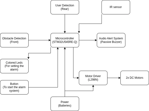
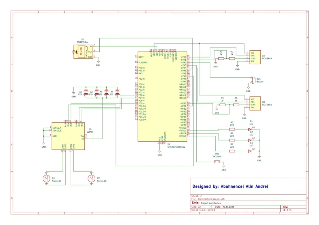
Architecture
Main Architectural Components:
- User and Obstacle Detection (Input Data):
- Role: Monitors surroundings to detect the user of pottential obstacles it may find in its way.
- Components: 2x HC-SR04 Ultrasonic Sensors. One is towards the user (rear side of the robot) and the other is towards the front.
- Logic: Signals are passed through a voltage divider (2K/1K resistors) to translate the 5V echo pin into 3V3 signals the board can accept.
- The Central Logic Controller (Processing):
- Role: The board executes the code logic, manages real-time interrupts from the sensors and calculates movement directions.
- Async Task Manager: Uses asynchronous programming to simultaniously handle the alarm timing, sensor signals and motor adjustments without blocking the CPU.
- Escape System (Output):
- Role: Responsible for the physical movement of the clock.
- Components: L298N Driver and 2x DC Motors.
- Control Logic: The board sends PWM signals to the EnA/EnB pins to control the speed and digital signals to pins IN1-IN4 to set the direction.
- Audio System (Output):
- Role: Provides an alarm sound that forces the user to interact with the device.
- Components: Passive Buzzer.
- Logic: It is triggered by GPIO pins when the internal RTC matches the set alarm time.
- Power Network:
- Role: Power the circuit accordingly to each component's needs.
- Logic: 1x external battery power the STM32 board and 4x AA batteries power the motors.
- Remote Control System (Input):
- Role: Allows the user to stop the alarm remotely.
- Components: Infrared Receiver and Remote Control.
- Logic: The receiver is connected to the board and listens for signals from the remote to trigger the alarm stop function.
- Visual Indicator System (Output):
- Role: Provides a visual countdown before the alarm goes off.
- Components: 3x LEDs.
- Logic: The LEDs light up in sequence to indicate the time left until the alarm is triggered.
Log
Week 13 - 19 April
- Bought the hardware necessary for the project.
- Defined the power management system.
Week 20 - 26 April
- Worked on the documentation, defining the architecture for the main features of the project.
Week 27 April - 3 May
- Started working on the hardware, setting up the breadboard and testing the sensors and motors separately.
Week 4 - 10 May
- Finished the hardware setup and started working on the software, implementing the basic logic for the alarm and the motor control.
Week 12 - 18 May
- Met the hardware deadline and presented the project during the lab session.
- Started working on the software, implementing the logic for the user and obstacle detection and the escape system.
Week 19 - 25 May
- Finished the software implementation and validated the project at the lab session.
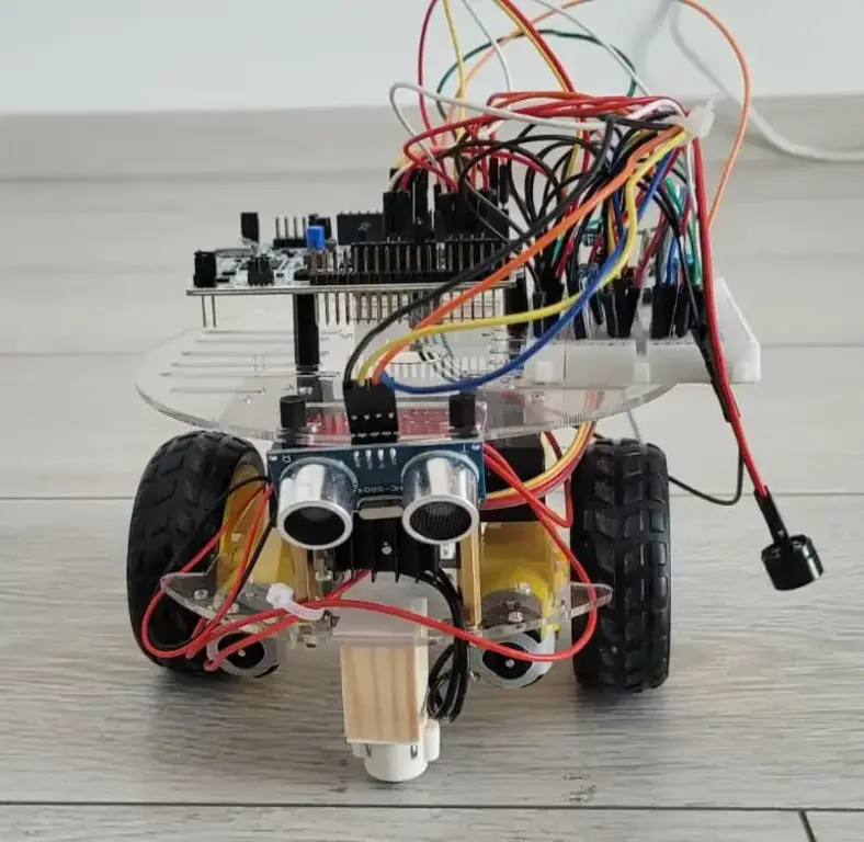
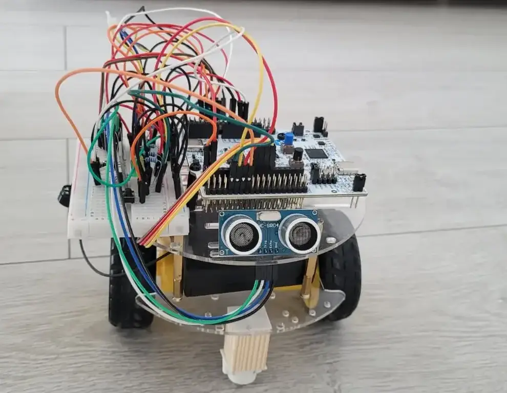
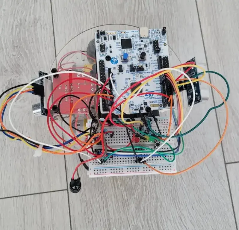
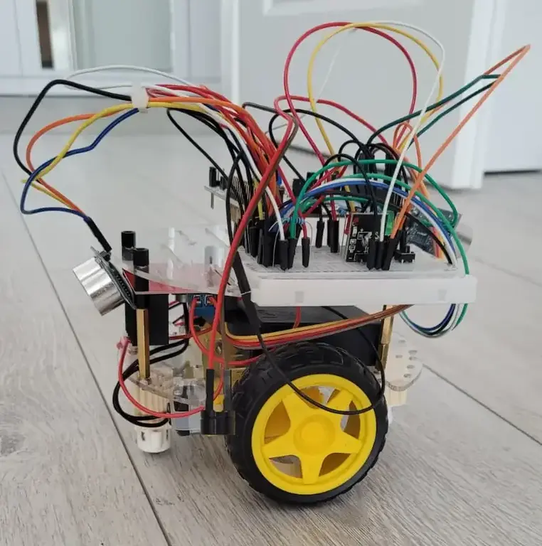
Hardware
- STM32 board: Responsible for processing the sensor data and controlling the motors and buzzer.
- HC-SR04 Ultrasonic Sensors: Used for detecting the user's presence and obstacles in the environment.
- L298N Motor Driver: Controls the speed and direction of the DC motors.
- DC Motors: Provide the physical movement for the clock to escape.
- Passive Buzzer: Emits the alarm sound to wake the user.
- Power Supply: A combination of an external battery for the STM32 board and AA batteries for the motors to ensure sufficient power for all components.
Schematics
Bill of Materials
| Device | Usage | Price |
|---|---|---|
| [STM32 Nucleo U545RE-Q] | The microcontroller | 110 RON |
| [Chassis Kit] | The base for the robot | 48.40 RON |
| [HC-SR04 Ultrasonic Sensor] x2 | Used for user and obstacle detection | 16.26 RON |
| [L298N Motor Driver] | Used to control the motors | 10.84 RON |
| [Passive Buzzer] | Used for the alarm sound | 1.45 RON |
| [LEDs] x3 | Used before the alarm starts to indicate the time left until the alarm goes off | 0.30 RON |
| [Resistors 220Ω] x3 | Used to limit the current to the LEDs | 0.10 RON |
| [Resistors 2k2Ω] x2 | Used for the voltage divider | 0.10 RON |
| [Resistors 5k2Ω] x2 | Used for the voltage divider | 0.10 RON |
| [Infrared Receiver] | Used to stop the alarm remotely | 4.84 RON |
| [Infrared Remote Control] | Used to stop the alarm remotely | 3.60 RON |
Software
| Library | Description | Usage |
|---|---|---|
| embassy-stm32 | Async HAL for STM32 microcontrollers | Provides hardware abstraction for peripherals like GPIO and EXTI |
| embassy-executor | Async executor for embedded | Manages and schedules concurrent async tasks (sensor, IR, LEDs, buzzer) |
| embassy-time | Time and delay primitives | Handles precise timing requirements (ultrasonic echoes, IR decoding, motor delays) |
| defmt | Deferred formatting framework | Highly efficient console logging, debugging, and printing |
| defmt-rtt | RTT transport for defmt | Transmits log messages to the host over Real-Time Transfer (RTT) |
| panic-probe | Panic handler for defmt | Catches panics and prints backtraces safely over the RTT channel |
| cortex-m / cortex-m-rt | ARM Cortex-M core crates | Low-level processor setup, core peripherals, and startup code |