TeddyBot
A wired animatronic toy that translates console commands into synchronized movements, audio and a pulsing LED heartbeat.
Author: Ivașcu Andreea-Daria
GitHub Project Link: https://github.com/UPB-PMRust-Students/acs-project-2026-Daria-Ivascu
Description
This project consists of an interactive animatronic system designed to demonstrate embedded hardware control through multi-sensory outputs. The physical structure is built around a 40-50 cm plush teddy bear, whose limbs have been detached at the major joints — shoulders, elbows, hips and knees — and reattached via external servo motor mounts, allowing precise and independent articulation of each limb. The input stage utilizes a wired console where user commands are captured through tactile button presses. Each button corresponds to a specific limb, sound or predefined animation routine, allowing the user to trigger individual movements. These routines can also incorporate synchronized audio playback, combining mechanical motion and sound into cohesive, expressive animations. During the processing stage, the STM32 Nucleo-U545RE-Q microcontroller translates these digital signals to evaluate logic, initiate specific motor actuation routines and fetch stored audio files. The output stage is multi-sensory: it produces precise mechanical limb articulation, outputs pre-recorded audio playback and uses light modulation to create a glowing, pulsating "heartbeat" effect in the toy's chest.
Motivation
The inspiration for this project stems from the desire to create technology that feels organic and approachable. Animatronics are widely used in entertainment, education and even therapeutic settings because of their ability to mimic life. The motivation here is to engineer a lifelike, interactive toy controlled via a wired interface. By programming the microcontroller to handle multiple routines simultaneously—triggering specific mechanical motions, playing contextual audio and modulating a glowing "heartbeat" - the project demonstrates how engineering and programming can be combined to build empathetic, interactive machines.
Architecture
The hardware system is centered around the STM32 microcontroller, which processes user inputs to drive physical actuators and generate audio-visual feedback.
Processing: The STM32 Nucleo-U545RE-Q handles all logic and signal generation. It connects to a PC via USB-C for flashing and debugging using ST-LINK/V3.
Power Management: A 5V powerbank serves as the primary power source, directly supplying the 5V rail for the servo motors through the PCA9685 driver. The STM32 microcontroller is also powered by the same source, utilizing its onboard voltage regulator to convert the 5V input into a stable 3.3V for the digital logic.
Communications:
- I2C: Used between the STM32 and the PCA9685 PWM driver for servo control commands.
- UART: Used between the STM32 and the DFPlayer Mini for audio playback commands.
- PWM: Generated by the PCA9685 for servo positioning and directly by the STM32 for LED modulation.
- GPIO: Used to read button inputs from the wired console.
Inputs:
- A wired console with tactile buttons connects to the STM32 via GPIO, allowing the user to trigger individual limb movements and predefined animation routines.
Outputs:
- PCA9685 PWM Driver: Receives commands from the STM32 via I2C and generates PWM signals for all 8 servos simultaneously.
- MG996R Servos ×4: Control shoulder and hip joints via PWM.
- SG90 Servos ×4: Control elbow and knee joints via PWM.
- DFPlayer Mini: Receives UART commands from the STM32 and plays pre-recorded audio files stored on a MicroSD card through an 8Ω 1W speaker.
- Red LED 10mm: Driven by a PWM signal to simulate a heartbeat pulse effect in the chest of the teddy bear.

Log
Week 14 - 20 April
- Finalized project theme and received approval
- Researched all hardware components
Week 27 April - 4 May
- Ordered all hardware components
Week 4 - 8 May
- Tested all the components to ensure they are working
- Created first drafts for the TeddyBot
Week 12 - 18 May
Week 19 - 25 May
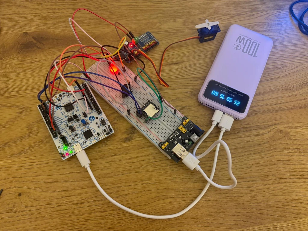
Hardware
The hardware centers on an STM32 microcontroller that orchestrates servo motors via an I2C PWM for movement, an MP3 module for audio, an LED for a heartbeat effect and a wired button console for user control.
Schematics
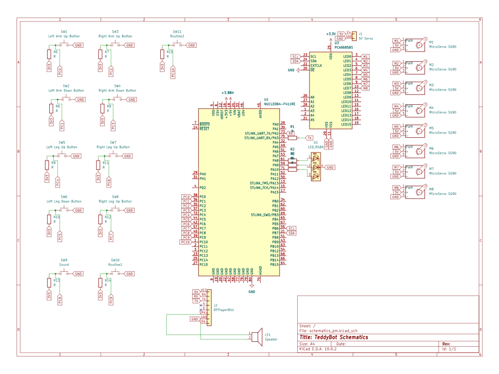
Bill of Materials
| Device | Usage | Price |
|---|---|---|
| STM32 Nucleo Board | Main Controller | Lab provided |
| MG996R Servomotor x4 | Main limb actuators | - |
| SG90 Servomotor x4 | Small extremity actuators | - |
| PCA9685 PWM Board | 16-channel I2C PWM driver for all servos | - |
| DFPlayer Mini | UART-controlled MP3 player module | - |
| MicroSD Card | Audio file storage | - |
| 10mm Red LED | Heartbeat visual effect | - |
| 1W 8-Ohm Speaker | Audio output for DFPlayer Mini | - |
| 10x Tactile Push Buttons | Wired console input for limb control | - |
| Powerbank 5V 20000mAh | Main power source for all components | - |
| ON/OFF Switch | Main power cutoff for the system | - |
| MB-102 Breadboard | Prototyping platform for all connections | - |
| Breadboard Power Supply | Power rail for breadboard | - |
| 50 cm Teddy Bear | Main body and physical casing of the robot | - |
Software
| Library | Description | Usage |
|---|---|---|
| embassy-stm32 | Hardware Abstraction Layer | Used for the display for the Pico Explorer Base |
| embedded-sdmmc | SD Card File System | Manages SPI communication and file system |
| mpu6050 | IMU Driver | Converting physical motion into digital angular data |