Claw Machine
An arcade claw machine that lets players grab prizes using a custom claw.
Author: Anca-Maria Stanciu
Github Project Link: https://github.com/UPB-PMRust-Students/acs-project-2026-Anca04-1
Description
The project is an interactive Claw Machine designed to grab and move objects. The claw is controlled by the user and can move in three directions: left-right (OX), front-back (OY) and up-down (OZ).
Players use buttons to move the claw over a prize, lower it, grip the object, and transport it to the drop area. The machine recognizes positional limits for safe and reliable operation, focusing on skill and timing for fun gameplay.
Motivation
The idea for this project started during a brainstorming session with a colleague. It brought back a personal memory from the end of high school when, after finishing my university entrance exam, I played at a claw machine to celebrate. I chose to build this project to recreate that experience.
Architecture
The project is divided into a few main parts that work together to make the claw machine move and grab prizes.
Main Components:
- The Controller: The main part of the machine (the STM32 board). It handles the arcade game's logic and coordinates all other parts.
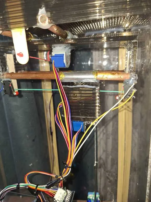
- The Movement System: Three motors are responsible for movement. They ensure the claw reaches the exact position above the prize and handle the up-and-down movement.
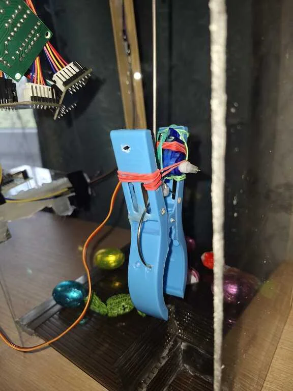
- The Grip System: The claw is powered by an SG90 servo motor that opens and closes it. This part is responsible for picking up the prize.
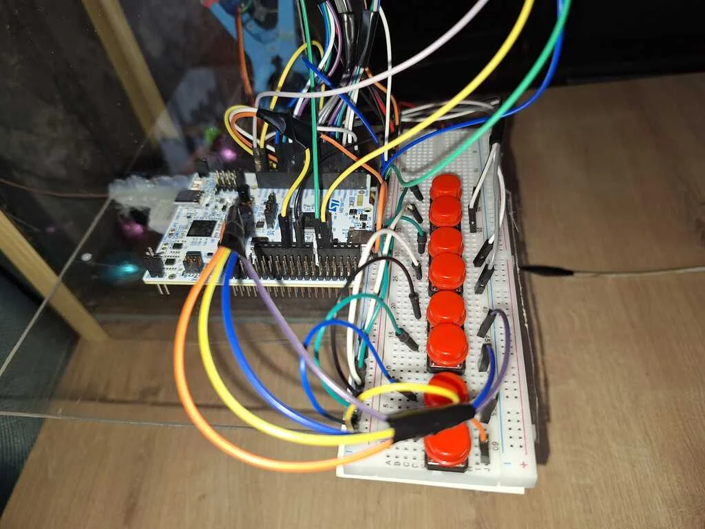
- The Buttons: A set of buttons integrated on a breadboard. These allow the player to move the claw on the OX, OY, and OZ axes and operate the grip.
- Boundaries: Small switches placed at the end of the axes (OX and OY). They signal the STM32 to stop the motors if the claw reaches the edge of the frame.

Log
Week 16 - 20 March
Defined the project concept and the list of components.
Analyzed the movement logic for the OX, OY, and OZ axes.
Researched the necessary limit switches for boundaries.
Week 23 - 27 March
Researched and selected the stepper motors to ensure the movement of the claw.
Selected the servo motor for the claw's opening and closing mechanism.
Chose a button-based interface instead of a joystick to avoid misalignment and ensure precise directional control.
Week 30 March - 3 April
Ordered the hardware components.
Week 6 - 11 April
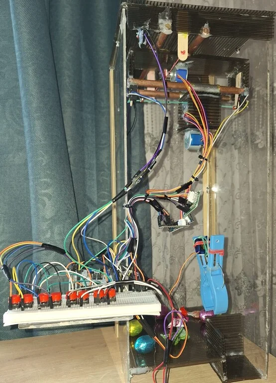
Built the casing and assembled the 3-axis system.
Assembled the claw and the gripping mechanism using the servo motor.
Connected the motors and limit switches to the STM32.
Developed the control code, testing each component individually.
Finalized the assembly and debugging of the entire project, resulting in a fully functional 3D claw machine.
Hardware
The project centers on the STM32 Nucleo board, the main controller. It processes button inputs and controls motor direction.
Main parts:
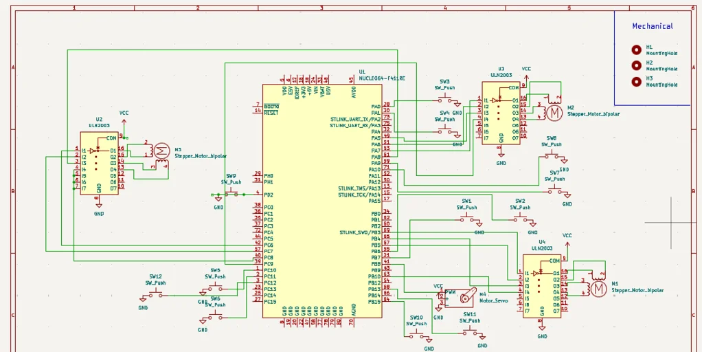
- STM32 Nucleo Board: This is the center of the machine. It receives signals from the buttons and tells the motors exactly how many steps to move. It also makes sure the claw doesn't hit the walls by checking the limit switches.
- 28byj-48 Stepper Motors and ULN2003 Drivers: I used three stepper motors for movement. These motors are great because they move in small, precise steps. Each motor has a driver (ULN2003) that acts as a bridge, supplying the power needed for the motors to spin. One motor moves the claw left/right, one moves it forward/backward, and the last one moves it up/down.
- SG90 Servo Motor: This small motor is located on the claw. Unlike the stepper motors, the servo is used only to open and close the claw. When you press the grab button, the servo turns to a specific angle to pick up the prize.
- Buttons: The player uses them to navigate the claw to the desired position.
- Limit Switches: These are very important for safety. If the claw reaches the end of the frame, it hits a switch. The switch sends a signal to the STM32 to stop the motor so the machine doesn't break.
- Power Supply: The stepper motors need more power than a simple USB cable from the laptop can provide. To solve this, I used a power adapter that connects to a wall outlet. This adapter converts the high voltage from the wall outlet to a safe 5V DC. This power goes directly to the stepper motors, ensuring they have enough strength to move the claw smoothly without overloading the STM32 board.
Schematics
Bill of Materials
| Device | Usage | Price |
|---|---|---|
| STM32 | The microcontroller | 110 RON |
| Stepper Motor and Drivers | Used for precise movement of the claw on the OX, OY, and OZ axes | 16.97 RON x 3 |
| SG90 Servo Motor | Operates the claw's gripping mechanism (opening and closing) | 13.99 RON |
| Micro Limit Switch | Acts as an endstop for axis safety | 5.23 RON x 4 |
| GT2 Timing Pulley - 20 Teeth, 5mm Bore | Connected to the motors to move the cords for each axis. | 4.67 RON x 3 |
| Breadboard | Used for organizing and connecting all electronic parts and power lines. | 11.30 RON |
| Plexiglass | Used to build the walls. | 70 RON |
| Polycarbonate Sheets | Used to build the floor and the system for the axis movement. | 20 RON |
| Total | 311.13 RON |
Software
| Library | Description | Usage |
|---|---|---|
| embassy-stm32 | Hardware Interface | Acts as a bridge between the Rust code and the physical pins (GPIO, PWM). |
| embassy-time | Time Management | Provides precise timing to control motor speed. |
| embassy-executor | Task Manager | Allows the system to run the main loop and handle inputs simultaneously. |
| defmt | Debug Logging | Used to send status messages to the computer for debugging. |
| panic-probe | Error Handling | Ensures that if the code crashes, the error is reported via the debug probe. |
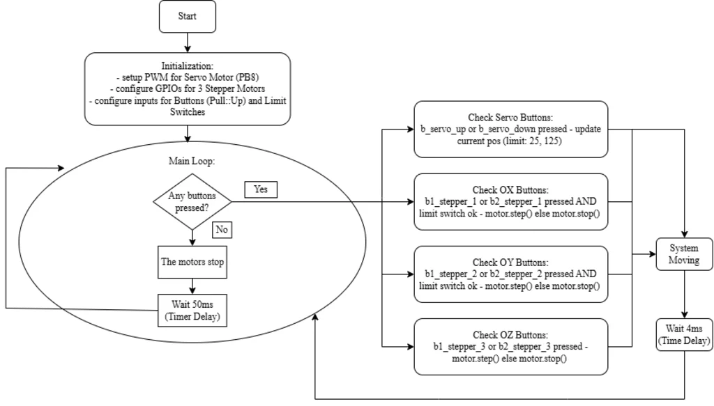
Key Implementation Details:
- Stepper Driver: Rather than using a generic library, I implemented a StepperMotor struct. This gives me direct control over the 8-step motor sequence, ensuring high precision.
- Movement Boundaries: Every movement command for the OX and OY axes is wrapped in a safety check. The motor only moves if the Limit Switch for that direction is not triggered.
- Servo Precision: The claw is controlled using PWM. The software limits the servo's movement between specific angles (25 to 125) to prevent mechanical strain on the claw.