Fire Prevention & Alarm System
Prevent wildfires by measuring relevant data and notifying authorities
Author: Răzvan-Ștefan Costea
GitHub Project Link: https://github.com/UPB-PMRust-Students/proiect-RazvanDire
Description
A system that takes periodic measurements of atmospheric pressure, temperature, humidity and light intensity levels. When a certain combination of parameters is reached, based on accepted scientific research, local authorities are notified and an alarm is started.
The system is intended to be used in areas that are arid and/or prone to wildfires. As such, the system runs on batteries and has a GPS module, so it can be located.
- two different sensors take the measurements
- the latest measurements are displayed on an LCD screen for passersby
- the Wi-Fi module allows the system to broadcast its coordinates, provided by the GPS module
- the audible-visual alarm is provided by a buzzer and flashing LEDs
Motivation
One of the biggest environmental threats that the modern world faces is global warming. The increase in temperatures and decrease in rainfall that result can cause massive wildfires, as we saw in California in January 2025. These wildfires destroy natural habitats and endanger thousands, which only exacerbates the problem further. The goal of my project is to identify conditions that might lead to wildfires and take preventive action, so we stop them before they happen. Furthermore, all the money and effort that would've gone towards putting out those fires and relocating people can be used to "cure" the root problem, global warming, instead of just "treating the symptoms".
Architecture

Log
Week 5 - 11 May
During the first week, I soldered the pins for all my components during the lab session. After that, I placed both Picos on the breadboard and managed to connect them by following the instructions in the datasheet.
I also connected one of the LEDs and the BME280 sensor and managed to get readings from it.
Week 12 - 18 May
In the second week, I connected the buzzer and activated it and the LED only when the temperature reached above a certain threshold. I also connected the TSL2561 sensor and wrote the code for it, getting readings.
After that, I configured the GPS module and had to do a lot of outdoors trips in order to get my location by sattelite.
Week 19 - 25 May
During the final week, I connected the LCD screen to the main circuit (it has no I2C, so I had to use the data lines directly) and managed to print text on it.
I added another LED an reconfigured a lot of my code in order to make the LEDs flash alternatively and the buzzer play an alarm only when certain parameters are reached and stop when within normal ranges.
Lastly, I used the Wi-Fi module of the Pico to host an endpoint to which I can connect to request sensor readings. The GPS coordinates are also sent on that connection when dangerous levels are reached.
Hardware
- Raspberry Pi Pico 2W:
- the microcontroller
- reads data from the sensors and activates the buzzer and the LEDs when certain parameters are reached
- sends the measurements to the LCD screen and the coordinates from the GPS via Wi-Fi
- BME280:
- pressure, temperature and humidity sensor
- takes periodic measurements and sends the data to the MCU
- TSL2561:
- light intensity sensor
- measures visible and infrared light intensity
- takes periodic measurements and sends the data to the MCU
- GY-NEO6MV2:
- GPS module
- provides the GPS coordinates of the system
- LCD screen:
- displays the data measured by the sensors for passersby
- Buzzer & LEDs:
- the audible-visual alarm: when certain parameters are reached, the alarm is triggered
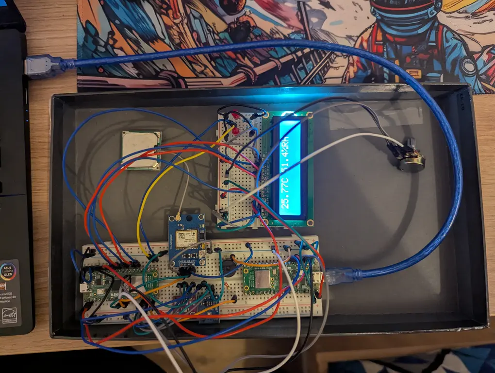
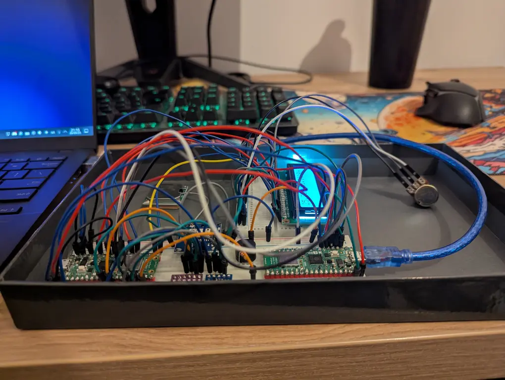
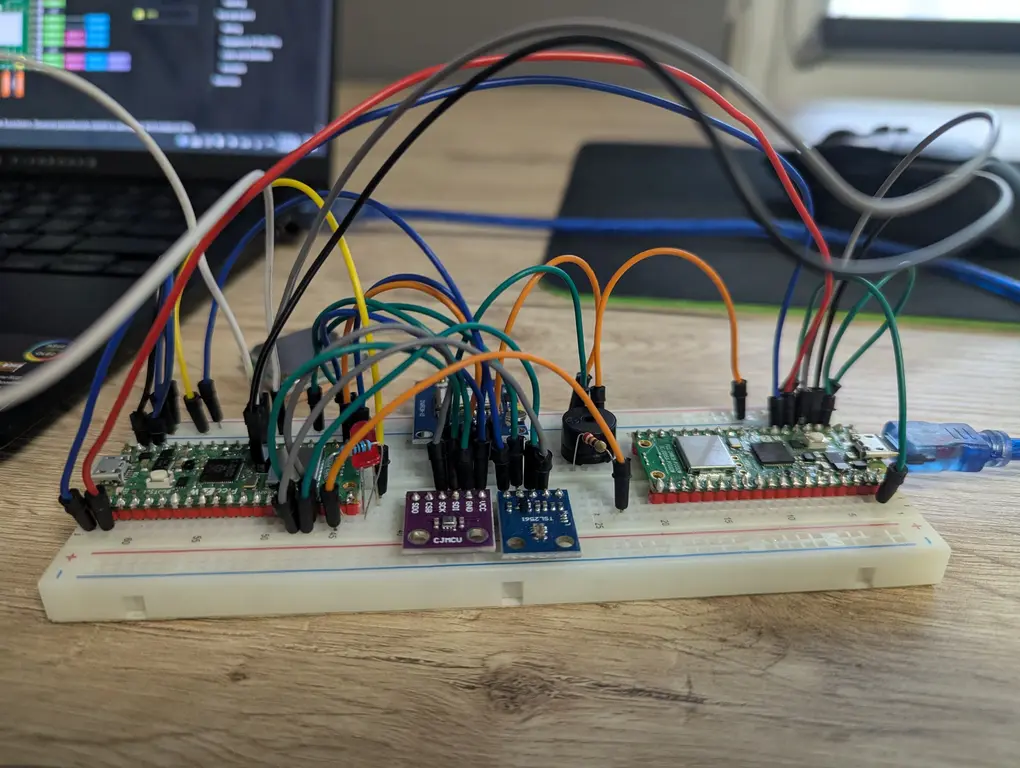
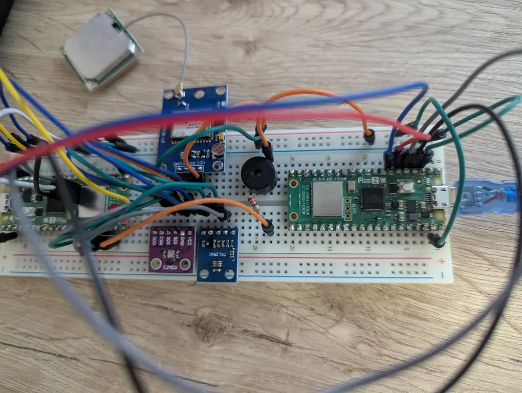
The first two photos showcase the main circuit: both Picos on the breadboard, connected accordingly, the BME280 and TSL2561 sensors, the GPS module, the LCD screen, the buzzer and the two LEDs. The last two pictures represent an earlier version of the project.
The video presents the current functionality of the project:
- the MCU constantly reads readings from both sensors and GPS module
- readings are displayed on the LCD screen
- when the temperature is above 26 °C, an alarm is started
- the alarm consists of a buzzer and LEDs that flash alternatively
Schematics

Bill of Materials
| Device | Usage | Price |
|---|---|---|
| Raspberry Pi Pico 2W | The microcontroller and debugger | 39.66 RON × 2 |
| BME280 | Pressure, temperature and humidity sensor | 73.99 RON |
| TSL2561 | Light intensity sensor | 22.99 RON |
| GY-NEO6MV2 | GPS Module | 44.95 RON |
| Potentiometer | Control the contrast of the characters on the LCD screen | 1.49 RON |
| Breadboard | Connect all the components | 9.98 RON |
| LCD screen | Display the sensors' measurements | 16.34 RON |
| Buzzer | Audio alarm | 1.40 RON |
| LED | Visual alarm | 0.39 RON × 2 |
| Pin header | Connect components to the breadboard | 0.99 RON × 3 |
| Battery holder | Power the circuit | 3.95 RON |
| Total | - | 258.16 RON |
Software
The flow of the code is as follows:
- The main task:
- sets up the network endpoint
- spawns the GPS, sensor, LED and buzzer tasks
- waits for connections from peers and for data from the sensors
- sends measurements to peers and the coordinates when there are dangerous levels
- updates the measurements with the data from the sensors, prints them to the screen and signals the LEDS and the buzzer when dangerous levels are reached
- The sensors task:
- configures the registers
- reads data from the sensors
- sends the measurements to the main task
- The GPS task:
- receives the sattelite data
- parses the data with the NMEA0183 protocol
- updates the geographic coordinates
- The LEDs task:
- waits for a signal from main
- flashes the LEDs alternatively while there are dangerous levels
- The buzzer task:
- waits for a signal from main
- plays an alarm while there are dangerous levels
Functional diagram

Dependencies
| Library | Description | Usage |
|---|---|---|
| embassy-rp | HAL targeting the RP2350 | Access to the peripherals |
| embassy-time | Timekeeping, delays and timeouts | Create timers |
| embassy-net | Async network stack | Send messages over Wi-Fi |
| embassy-executor | An async/await executor | Create different tasks |
| embassy-sync | Synchronization primitives with async support | Communication between tasks |
| embassy-futures | Utilities for working with futures | Select the first of multiple futures |
| ag_lcd | Display library | Used for my 16 characters on 2 lines LCD screen |
| heapless | Statically allocated data | Used to write strings for my LCD and to peers |
| tsl256x | Platform agnostic driver for TSL256x | Read raw data from TSL2561 |
| libm | libm in pure Rust | Use mathematical functions, such as pow |
| nmea0183 | NMEA 0183 parser targetting embedded devices | Parse sattelite data from GPS module |
| static-cell | Statically allocated, initialized at runtime cell | Send arguments from main to tasks |