Pip-Boy 2000
Wrist-mounted device that displays various info on a screen.
Author: Matei Rareș-Andrei
GitHub Project Link: Pip-Boy 2000
Description
Pip-Boy 2000 is a device that is mounted on someone's wrist and contains various sensors and modules in order to track the wearer's well being and the surrounding environment. The recorded data is displayed on a LCD screen and the wearer can cycle through it by pressing buttons on the device. To ensure the device's safety, to be used it needs to scan the wearer's fingerprint when mounted.
Motivation
I always wanted to try tech from games I played or that fascinated me and the Fallout universe is one of the most interesting worlds in gaming fiction, so I thought that I should try to build something from it and the Pip-Boy 2000 seemed the obvious choice.
Architecture
Log
Week 5 - 11 May
Docs week
Week 12 - 18 May
Hardware week
I changed the fingerprint sensor with a capacitive one that requires 3.3V and is using I2C.
I was unsure if I needed a step-down and a logic level translator for the pulse sensor but I found out that the component I bought already has LDO to lower the voltage to 1.8V, so the module works with the 3.3V from the pico.
I did the sum of all currents used by the modules to see if the pico can power them.
| Module | Current |
|---|---|
| GY-BMP280 | 4.2 * 10^-3 mA |
| GPS GY-NEO6MV2 | 10 mA |
| MAX30100 | 1.2 mA |
| SKU SEN0359 | 60 mA |
| LCD Screen | 3 + 20 mA |
| Total | ~100 mA |
From pico datasheet: "3V3 is the main 3.3V supply to RP2350 and its I/O, generated by the on-board SMPS. This pin can be used to power external circuitry (maximum output current will depend on RP2350 load and VSYS voltage; it is recommended to keep the load on this pin under 300mA)."
This table from the rp2350 datasheet also indicates this.
I also uploaded a KiCad schematic of the circuit.
For the wiring I tried to match the wires:
Orange - VCC
Gray - GND
Green - SCL / SCK / TX
Blue - SDA / RX
Red - CS and RESET from the LCD screen
Yellow - A0 from the LDC screen / INT from MAX30100
Black - Button pins
Week 19 - 25 May
Software week
I started the software part by programming the bmp280 as we used it in a lab. At first I used that code but I found the bme280-rs crate that also works with bmp280 and it made the code easier. Then I continued with the lcd screen as we also used one of those in a lab. Initially I tried to use the st7735-lcd-rs crate thinking it will be easy as it was named after the module, but I didn't manage to get it to work, so I rolled back to use the mipidsi crate used in the lab and it worked fine.
Next I programmed the buttons to cycle through the screens. I used a mutex to hold the index of the current page and created 2 tasks, one for each button, that loop infinitely while waiting the button to be pressed. In the main loop I take the value from the mutex and match it to select what to display on the screen. I also programmed the GPS but it says that it doesn't have signal.
For the fingerprint sensor I needed to do the crate myself, I found the official repository with the Cpp code and I tried to convert the minimum ammount I needed into Rust code. I did 2 functions, one to save a fingerprint and one to identify, but I didn't manage to understand the packets sent from the sensor to the pico, so unfortunately it doesn't work.
I also needed to create a crate for the pulse sensor, as the one on crates.io is blocking and it doesn't work in my project. I didn't have much time with this one so I tried to do something else.
Lastly I implemented a clock in this device by counting the seconds starting from the start of the code and adding the time saved when building the project.
Hardware
- Raspberry Pi Pico 2W
- Processes the data recieved from the sensors and sends it to the screen
- Stores GPS coordinates that the wearer wants saved
- Barometric Pressure Sensor GY-BMP280
- Measures atmosferic pressure and temperature
- GPS GY-NEO6MV2 with antenna
- Uses radio waves and satelite navigation to determine coordinates
- Pulse Sensor MAX30100
- Measures the wearers pulse
- Gravity Capacitive Fingerprint Sensor SKU SEN0359
- Used to start the device, only reacts to wearer's fingerprint
- LCD Screen 1.44 inch diag (128x128 px)
- Displays data from the sensors, can cycle through multiple screens
- Other stuff
- Batteries, wires, breadboard, buttons
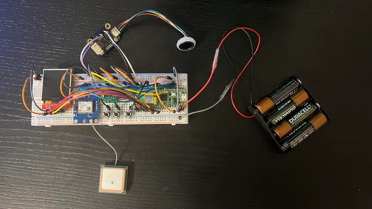
This is the device's circuit. I need to make a small case to hide the wires and the components, except the screen, fingerprint sensor, pulse sensor and the buttons.
Schematics

Bill of Materials
| Device | Usage | Price |
|---|---|---|
| Raspberry Pi Pico 2W | Processing power | 39.66 RON |
| Barometric Pressure Sensor GY-BMP280 | Pressure and temperature sensor | 8.49 RON |
| GPS GY-NEO6MV2 with antenna | Tracks GPS coordinates | 44.95 RON |
| Pulse Sensor MAX30100 | Monitors wearer's pulse | 24.99 RON |
| Gravity Capacitive Fingerprint Sensor SKU SEN0359 | Scans wearer's fingerprint to start the device | 184.79 RON |
| 1.44'' LCD Screen | Displays data from the sensors | 27.99 RON |
| Other stuff (breadboard, wires, battery, buttons) | Used to assemble the device | 60 RON |
| Total | - | 390.87 RON |
Software
| Library | Description | Usage |
|---|---|---|
| embassy-rp | HAL implementation to not use registers directly | Gives access to GPIO, I2C, SPI ports |
| bme280_rs | Driver for the Bosch BME280 sensor to query temperature, pressure and humidity, also works with the BMP280 | Tracks temperature and atmospheric pressure |
| ublox | Library for uBlox GPS devices | Tracks GPS coordinates |
| mipidsi | Generic display driver that supports the ST7735-LCD Screen model | Displays data on screen |