Light tracker with solar pannel & LEDs
A one line project description
Author: Daria-Catalina Banu
GitHub Project Link: https://github.com/UPB-PMRust-Students/proiect-Scarlett-stack
Description
A system that follows the most intense light source using photoresistors and rotates and translates vertically a mini-solar panel to maximize light capture.
Motivation
I chose this project because it allows me to explore embedded systems through a practical application that combines environmental awareness with precise motion control. Using stepper motors to orient a solar panel towards the most intense light source offers both a technical challenge and an opportunity to improve energy efficiency. This project also gives me hands-on experience with ADCs, real-time light tracking, and low-level motor control using Rust and the Embassy framework.
Architecture
-
Light Sensor Module (ADC Sampling + Filtering) Continuously reads values from 4 photoresistors (via ADC), applies a basic smoothing/filtering algorithm, and computes which direction has the strongest light intensity.
-
Motor Control Module Controls two stepper motors for horizontal and vertical movement. Uses a state machine to determine the required movement based on the output of the light sensor module.
-
Tracking Algorithm Coordinates input from the sensors and sends precise motor commands. Includes logic for tolerance thresholds, and movement limits.
-
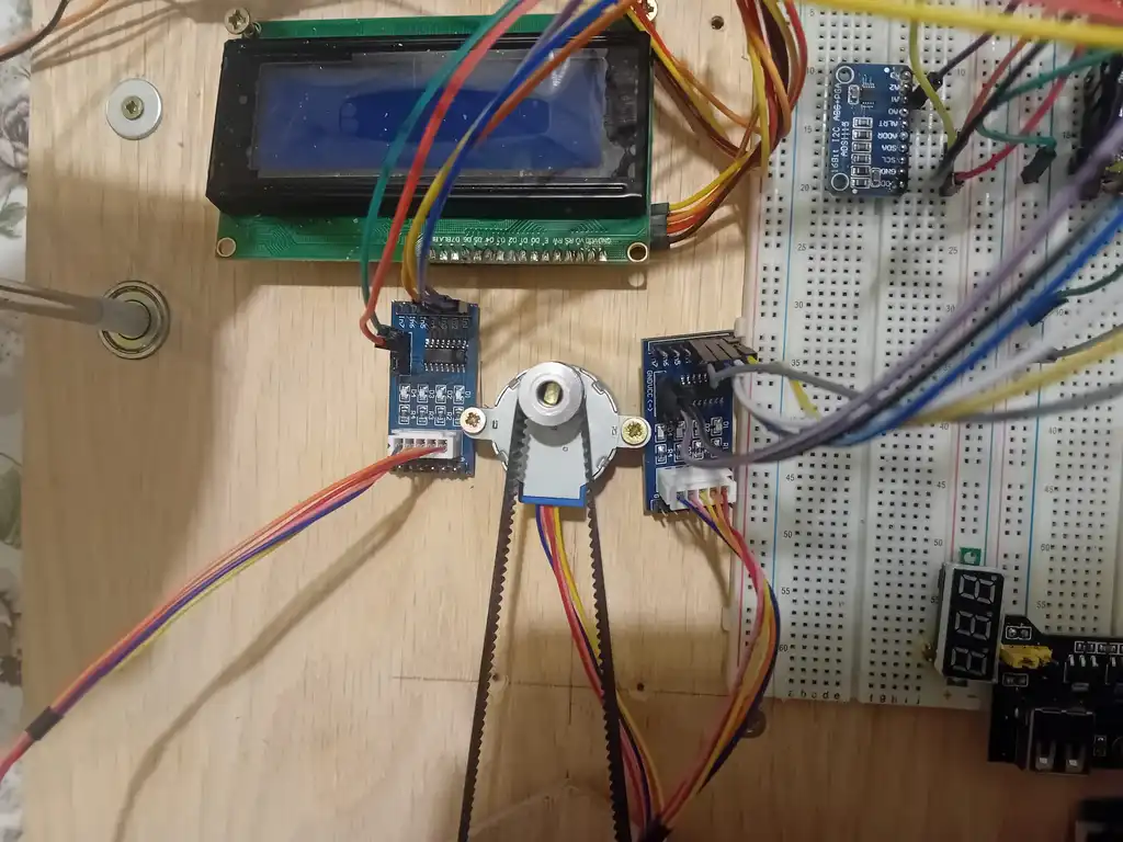
Display Module Shows real-time status info (e.g., direction, light levels, current position) on the LCD2004 screen using pcf8754T module and i2c-characther-display crate
-
Debug & Logging (defmt) All internal states, sensor readings, and motor steps are logged via RTT for debugging and tuning purposes.
Log
Week 21 – 27 April
Ordered hardware components updated the project's initial diagram, and also started exploring some rust crates compatible with my components.(uln2003, ads1x1x)
Week 28 April – 4 May
I tested some of the components on the breadboard to see if they work properly. (ky-018 photoresistor module, ads1115 adc convertor). I am also thinking of using a port expansion module for the led band, in case i run out of gpios on the pico.
Week 5 - 11 May
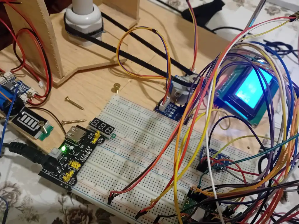
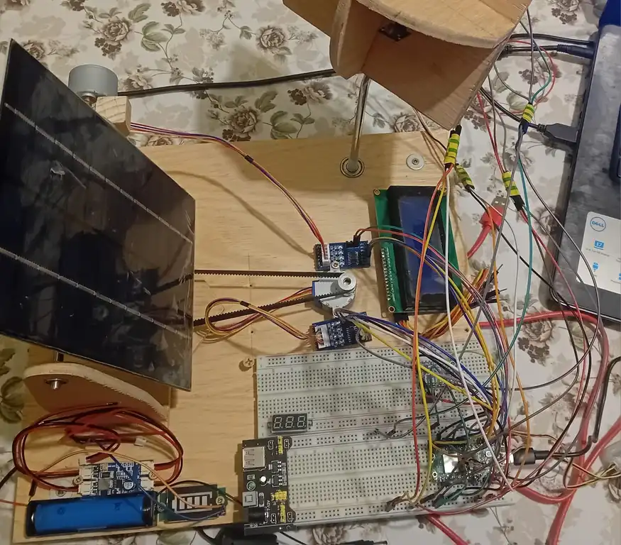
Assembled everything on the breadboard using screws and also built a wooden support for the pannel, the breadboard , accumulator , solar pannel and the 4 photoresistor modules. I decided to use a transmission belt and a pulley for the vertical rotation stepper, since i didn't find the necessary pieces to attach the stepper directly to the bottom of the horizontal plane. Wrote code to test the steppers, lcd and ads.
Week 12 - 18 May
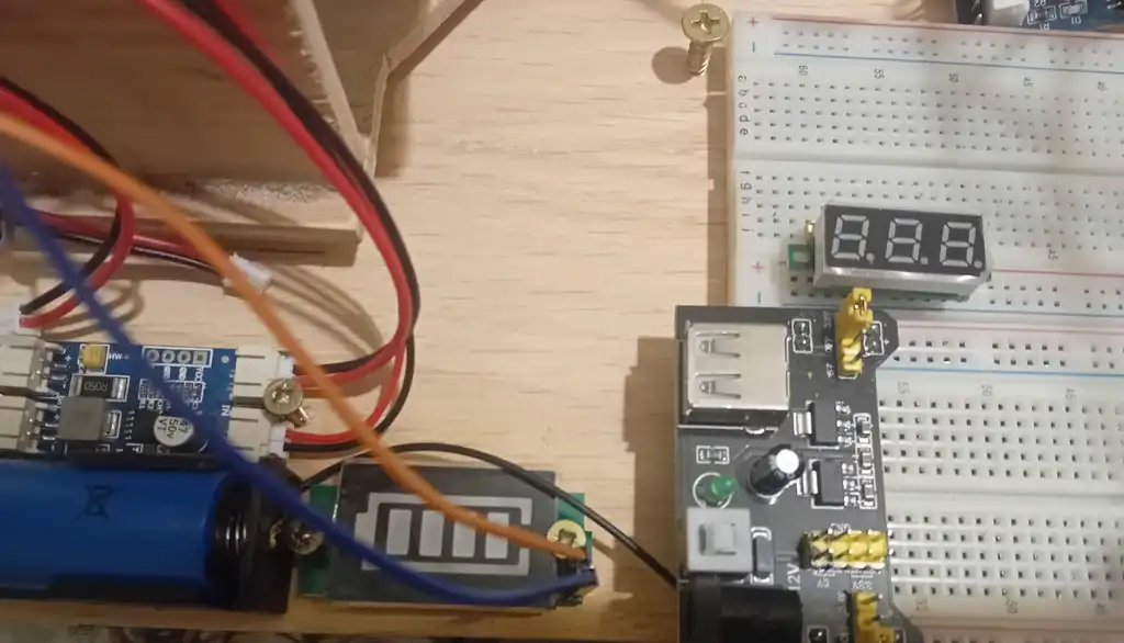
I started using a power supply for breadboard module which can provide 5V or 3v3 depending on how I want to configure it. I actually measured the output and apparently it gives around 6V and 4V respectively. I might have accidentally burned the ADS when I connected it to the 5v power rail on the breadboard , because it kept outputting negative values, and as an emergency solution I decied to move 3 photoresistor modules back on the pico and keep only one on the ads. I replaced the old ads with a new one and it seems to work now. I still need to figure out a better approach to detect light fluctuations.
Week 19 - 25 May
Implemented the full code , I decided to compute the averages on each analog channel then again average left, right, top bottom, choose minimum and rotate towards it. Calculated a threshold value expermientally, but it can be changed if need be. Sadly due to steppers being steppers and the way I designed the pannel support I decided to implement limitations for movement to not destroy the solar pannel or other hw components placed in the proximity. Also I had to fixate with screws the supporting tube because the transmission belt kept loosing momentum due to this tube's lack of proper fixation on the wooden support. I also added a few leds for fun. The voltmeter only outputs if there is enough light for the pannel to produce 4 V , i think i wasted my money on it :( .
Hardware
-
Raspberry Pi Pico 2W – The main microcontroller that runs the firmware using Rust and the Embassy async framework.
-
Raspberry Pi Pico Debug Probe
-
4× Light Sensors + ADS1115 ADC – Used to sense light intensity from different directions. The ADS1115 allows me to read data from the 4 modules
-
2× Stepper Motors (28BYJ-48) + ULN2003 Drivers – Control the rotation and tilt of the solar panel. Each motor is driven by a ULN2003 driver module.
-
LCD2004 Display – Displays real-time tracking information. Controlled using the hd44780-driver crate over I²C.
-
Battery Level Display Module
-
Accumulator
-
Mini Solar Panel – Rotates to face the brightest light source. Mounted on the motor platform.
-
Transmission Belt – Used to rotate horizontally the solar pannel support.
-
6mm 15 Tooth Pulley
-
Breadboard, jumper wires, resistors – For prototyping and building the circuit.
Schematics

Bill of Materials
| Device | Usage | Price |
|---|---|---|
| Raspberry Pi Pico 2W | The main microcontroller | 39.66 RON |
| ADS1115 ADC Module | 16-bit analog-to-digital converter for photoresistors | 32.98 RON |
| KY-018 Photoresistor Module (x4) | Detects light intensity from different directions | 9.12 RON |
| 28BYJ-48 Stepper Motor (x2) | Provides panel rotation and tilt | 33.94 RON |
| ULN2003 Driver Module (x2) | Drives the stepper motors | inclus in stepper |
| LCD2004 Display with I²C | Displays real-time tracking status | 26 RON |
| PCF8574 I²C Port Expander | Optional I/O expansion for controlling LEDs | 9.99 RON |
| LEDs | Visual feedback on light intensity (1 green , 1 rgb) | 1 RON |
| Mini Solar Panel | panel that follows light | 18 RON |
| Breadboard, wires, resistors, wood, screws and pulleys | Prototyping and circuit building | ~40 RON |
| MPPT Solar Charging module CN3065 | To load accumulator | 8.35 RON |
| Indicator Tensiune pentru Acumulatori (4s) | To display battery level | 9.99 RON |
| Voltmetru | Display pannel voltage | 10.99 RON |
| Suport baterie | to place accumulator in it | free (found it in my home) |
| Sursa de alimentare pentru breadboard | to fire up steppers and lcd and sensors | 4.69 RON |
| Light sensor | to detect light variations | 4 x 3.20 RON |
| Debug Probe | debug | free (found it in my home) |
Estimated Total: 190.69 RON
Software
| Library / Crate | Description | Usage |
|---|---|---|
| embassy | Async embedded framework for Rust | Used for async task scheduling and peripherals |
| embassy-rp | Embassy HAL implementation for RP2040/RP2350 | Used for GPIO, ADC, PWM, I²C on the Pico W |
| embassy-time | Timing utilities for async delays | Used for blinking LEDs, servo control, debouncing |
| embassy-sync | Async-safe synchronization primitives | Coordination between async tasks (e.g., tracking + UI) |
| defmt | Lightweight logging framework | Used for debugging over RTT |
| defmt-rtt | Transports defmt logs over Real-Time Transfer | Debug output |
| panic-probe | Panic handler with defmt logging | Used to capture and print panics in embedded code |
| ads1x1x | Driver crate for ADS1115/ADS1015 ADCs | Used to read analog values from photoresistors |
| hd44780-driver | Driver for HD44780-based displays (like LCD2004 via I²C) | Used to display data on LCD screen |
| embedded-hal-async | Async traits for embedded-hal peripherals | Required by embassy for async I²C, ADC, etc. |
| project/daria_catalina.banu | ||
| uln2003 | to control steppers crate | need to control steppers |
| i2c-character-display | to display on lcd2004 | display |