Speed gun
Portable speed detection device.
Author: Rîpeanu Constantin-Adrian
GitHub Project Link: https://github.com/UPB-PMRust-Students/proiect-RipeanuAdrian
Description
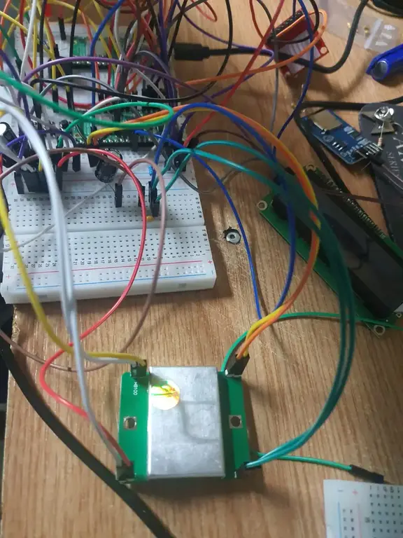
A portable radar device that uses a Doppler sensor to measure the speed of moving objects. If the detected speed exceeds a configurable threshold, it activates a buzzer, lights up a red LED, and captures a picture using an OV2640 camera module.
-
The measured speed and speed limit are shown on an LCD 1602 I²C display.
-
The reference speed can be adjusted using physical buttons.
-
When speed is within the safe range, a green LED is lit.
-
When overspeed is detected, the red LED lights up and a buzzer sounds.
-
The image is stored on a microSD card or sent over WiFi via a Telegram bot or HTTP request.
Motivation
This project allowed me to explore embedded systems and real-time hardware control using Rust. I wanted to build something educational and practical — a compact device that detects motion and responds automatically.
I chose this topic because fixed speed cameras are a current subject, especially with the rollout of systems like “e-Sigur”. Inspired by how real traffic radars work, I aimed to recreate a simpler, portable version that can measure speed and take photos.
Arhitecture

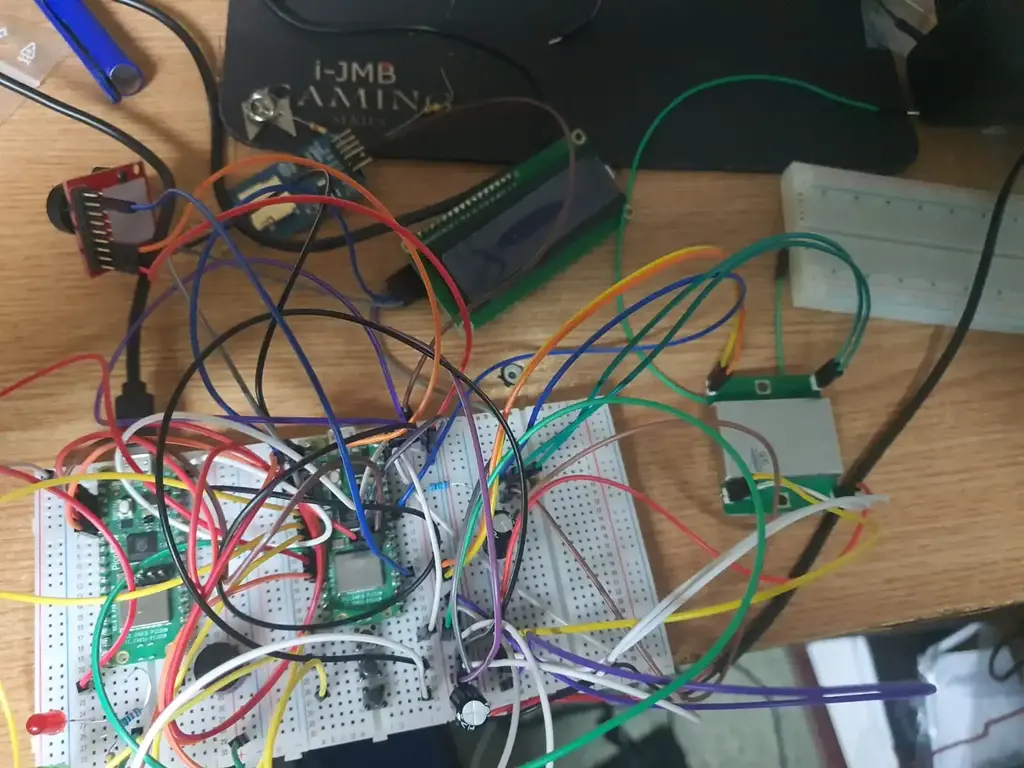
The Raspberry Pi Pico 2W acts as the core of the system, coordinating all modules:
The HB100 Doppler sensor detects motion and outputs a frequency that reflects the speed.
An LM358 op-amp amplifies the Doppler signal to be read via ADC.
The LCD 1602 I²C displays the measured speed and configurable speed limit.
OV2640 camera captures an image when overspeed is detected.
The microSD card module stores the image, while WiFi can send it to a remote server or Telegram.
Buttons allow manual adjustment of the speed threshold.
LEDs indicate if the detected speed is within or above the limit.
A buzzer sounds on overspeed detection.
Log
Week 1 – May 6–12
- Chose the project topic: a speed measurement system using the HB100 radar sensor.
- Studied documentation for the HB100 module and its compatibility with the RP2040 Pico W board.
- Created the initial wiring plan (breadboard layout and power distribution).
- Began the schematic documentation using KiCad.
- Set up the development environment: Embassy + probe-rs + defmt logging.
- Wrote a simple test program to verify GPIO functionality and LCD output.
Week 2 – May 13–19
- Purchased the following components:
- HB100 radar sensor
- LCD 1602 with I²C interface
- 5V active buzzer
- Tactile push buttons
- LEDs and resistors (220 Ω, 10 kΩ)
- Capacitors (10 nF, 220 µF)
- Jumper wires and large breadboard
- OV2640 camera module (for future use)
- Tested the HB100 sensor in both digital and analog modes using RP2040 and defmt logging.
- Partially completed the KiCad schematic:
- Added components: RP2040 Pico, HB100, LCD, buzzer, buttons, and LEDs.
- Learned how to add, rename, and manage components in KiCad.
- Analyzed HB100 behavior with and without filtering (resistor + capacitors).
- Clarified the power supply layout: +5V on RR, GND on RB, common ground with Pico.
- Documented all necessary pin connections for the Pico board in the project setup.
Week 3 - May 20-27
-
Implemented the software for the hardware setup.
Hardware


-
Raspberry Pi Pico 2W
– Acts as the main controller and WiFi client -
HB100 Doppler Radar Sensor
– Measures object speed via frequency shift -
LM358 Operational Amplifier
– Amplifies weak IF signal for ADC processing -
LCD 1602 with I²C Adapter
– Displays speed and settings -
OV2640 Camera Module
– Captures images when threshold is exceeded -
microSD Card Module
– Stores JPEG images locally -
Buzzer
– Audible alert when speed is exceeded -
Red & Green LEDs
– Visual status indicators -
Push Buttons (×3)
– Adjust speed threshold and trigger capture -
Logic Level Shifter
– For safe I²C communication (LCD module at 5 V, Pico at 3.3 V) -
Breadboard & jumper wires
– Rapid prototyping and testing -
External 5 V USB Power Supply
– Ensures sufficient power for all componentsSchematics
Bill of Materials
| Device | Usage | Price |
|---|---|---|
| Raspberry Pi Pico 2W | Main microcontroller, handles all components and WiFi | 39,66 RON |
| HB100 Doppler Radar Sensor | Measures object speed via Doppler shift | 19,99 RON |
| LM358 Operational Amplifier | Amplifies low-frequency IF signal from HB100 | 2,40 RON |
| OV2640 Camera Module | Captures images when speed exceeds threshold | 51,28 RON |
| LCD 1602 I²C Display | Displays measured speed and configurable speed limit | 16,34 RON |
| microSD Card Module | Stores captured images on microSD card | 4,08 RON |
| microSD Card 16 GB | Storage medium for image files | 39,99 RON |
| Level Shifter 3.3V ↔ 5V (TXS0108E) | Enables safe I²C communication between Pico and 5V devices | 3,99 RON |
| Breadboard 400-point | Rapid prototyping without soldering | 4,56 RON |
| Jumper Wires (Male–Male) | Connects components on breadboard | 7,99 RON |
| Push Buttons 6×6×6 mm | Used for user input (threshold control & manual trigger) | 2,16 RON |
| Red & Green LEDs 5mm | Visual indicators for speed status | 2 RON |
| Buzzer | Audible alert for overspeed detection | 1,98 RON |
| Resistors (10 kΩ, 220 Ω) | Pull-up resistors, current limiting for LEDs and filters | 1 RON |
| Condensator 10 nF ceramic | Filter for Doppler signal smoothing | 2,34 RON |
Software
| Library | Description | Usage |
|---|---|---|
| embassy-rp | RP2040 HAL + async executor support | Low-level access to GPIO, I²C, timers and board initialization (init, Input/Output, I2C) |
| embassy-executor | Async task executor for embedded | #[embassy_executor::main] entry point, task scheduling |
| embassy-time | Async timers and delays | Timer::after(...) and Delay types for non-blocking waits |
| embedded-hal | Hardware abstraction traits | Underlying trait layer used by embassy-rp for GPIO/I²C interfaces |
| defmt-rtt | Real-time logging over RTT | defmt::info! for printing debug/log messages via probe |
| panic-probe | Panic handler that logs via RTT | Catches panics and reports stack trace over RTT |
| hd44780-driver | HD44780-based LCD over I²C | Drives the 16×2 character display (lcd.clear, lcd.write_str) |
Detailed Design
1. Reference Speed Control
- Libraries used:
embassy-rp::gpio,embassy-time - Responsibilities:
- Read “+” and “–” buttons with 50 ms debounce (
Timer::after) - Increment/decrement the
ref_speedvariable - Update the LCD only when
ref_speedchanges
- Read “+” and “–” buttons with 50 ms debounce (
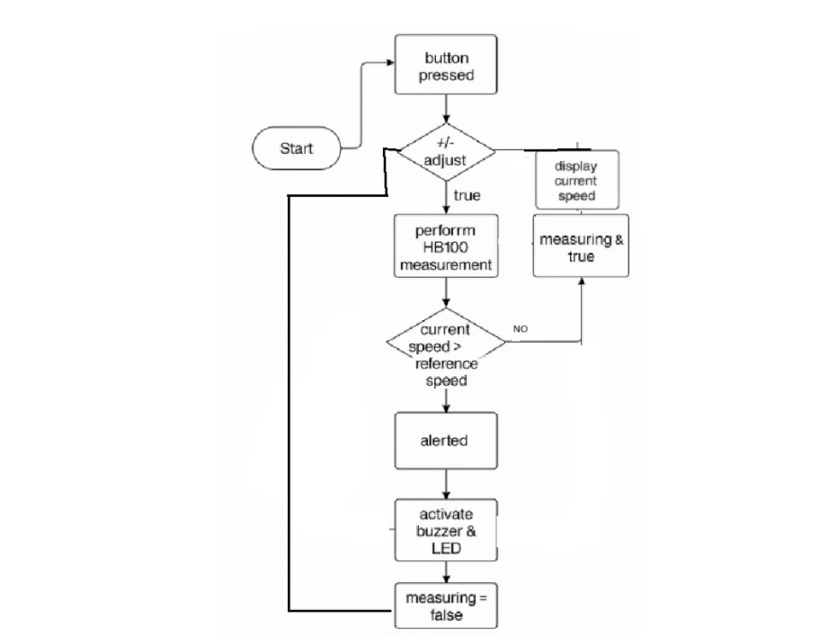
2. Measurement Control
- Libraries used:
embassy-rp::gpio,embassy-executor - Responsibilities:
- Toggle measurement on/off with the “Start” button
- Manage
measuringandalertedflags to coordinate measurement cycles and one-time alerts
3. Doppler Sensor Task
- Libraries used:
embassy-rp::gpio,embassy-time - Responsibilities:
- Sample the HB100 IF pin for
GATE_MS = 200 ms, counting falling edges - Compute Doppler frequency
f_d = pulses * (1000 / GATE_MS) - Apply threshold filter (
MIN_F_HZ = 80 Hz) - Convert to speed in km/h:
v = 0.5 * f_d * λ * 3.6
- Sample the HB100 IF pin for
4. Display Manager
- Libraries used:
embassy-rp::i2c,hd44780-driver,heapless::String - Responsibilities:
- Initialize I²C and the 16×2 HD44780 LCD over address
- Clear display, position cursor, and write formatted “Ref: X km/h” and “Cur: Y km/h” lines
- Use
heapless::String<16>to build strings without heap allocation
5. Alert System
- Libraries used:
embassy-rp::gpio,embassy-time - Responsibilities:
- On
measuring && current_speed > ref_speed && !alerted: - Generate 100 PWM cycles on the buzzer
- Blink the red LED for 500 ms
- Clear the current‐speed line on the LCD
- Stop measuring and set
alerted = true
- On