Pico Access and Cloning System (PACS)
A compact embedded solution for secure credential cloning and local access control
Author: Abdulkadir Gobena DENBOBA
GitHub Project Link: https://github.com/UPB-PMRust-Students/proiect-denboba
Description
PACS (Pico Access and Cloning System) is a compact and cost-effective embedded system designed to facilitate secure credential cloning and local access control. Built on the Wi-Fi-capable Raspberry Pi Pico 2W, PACS serves as a versatile solution for managing physical access to secured environments such as residences, offices, and dormitories.
The system supports cloning of contactless smart cards (e.g., MIFARE Classic) and enables the configuration of authorized credentials for entry control. It can be used in two modes: User Mode acting ass access system or Admin Mode acting as cloning system. it can also be used with a smartphone giving users more convenience
Motivation
For my PM project, I wanted to work on a practical and real-world-relevant solution, and I could not find something more suitable for my level than PACS. In many institutions—such as student dormitories—each resident is issued a smart card to gain entry. Replacing or duplicating these cards is often costly (typically 20 RON per card) and time-consuming. PACS addresses this by allowing trusted users or administrators to securely clone authorized cards directly from the device and even use smartphones (via card emulation) as digital credentials with no cost. This not only saves time and money but also enhances convenience and security by eliminating unnecessary intermediaries.
Architecture
Schematic Diagram
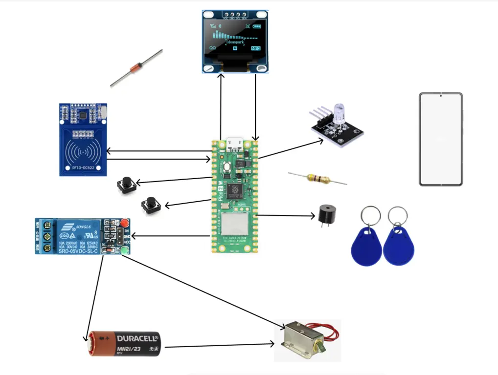
Components and Connections
Raspberry Pi Pico and RC522 RFID Module (SPI Communication)
| RFID (RC522) | Raspberry Pi Pico 2W | Notes |
|---|---|---|
| VCC | 3.3V | |
| GND | GND | |
| RST | GP6 | Reset(Optional) |
| SDA (SS) | GP5 | SPI Chip Select |
| MOSI | GP3 | SPI Data Out |
| MISO | GP4 | SPI Data In |
| SCK | GP2 | SPI Clock |
The RFID module is used for reading and cloning card credentials. It communicates with the Raspberry Pi Pico via SPI. Raspberry Pi Pico is the main controller that manages the entire system.
Relay Module AND Raspberry Pi Pico
| Relay Module | Raspberry Pi Pico 2W | Notes |
|---|---|---|
| IN | GP7 | Activates solenoid |
| VCC | VSYS (5V) | Power for relay module |
| GND | GND | Common ground |
| NO (Normally Open) | Solenoid (-) | Activates lock when relay is triggered |
| COM (Common) | 12V Power Source (-) | Shared ground for solenoid and relay |
| Flyback Diode | Across solenoid terminals | 1N4007: Cathode → 12V+, Anode → GND |
The relay module is used to control the solenoid lock. The Raspberry Pi Pico sends a signal to the relay to activate the lock.
Display Module and Raspberry Pi Pico (I2C Communication)
| OLED (I2C) | Raspberry Pi Pico 2W | Notes |
|---|---|---|
| VCC | 3.3V | |
| GND | GND | |
| SDA | GP16 (I^2C1) | Avoid GP0/GP1 (debug conflict) |
| SCL | GP17 (I^2C1) |
The display module is used for user interaction and feedback. It communicates with the Raspberry Pi Pico via I2C.
Buzzer Module and Raspberry Pi Pico
| Buzzer | Raspberry Pi Pico 2W | Notes |
|---|---|---|
| + | GP8 | |
| - | GND |
The buzzer module provides audio feedback for various events in the system, such as successful cloning or access denial.
Push Button and Raspberry Pi Pico
| Button | Raspberry Pi Pico 2W | Notes |
|---|---|---|
| User (GP12) | → GND | Internal pull-up |
| Admin (GP13) | → GND |
The push button is used to switch between user and admin modes. The Raspberry Pi Pico uses internal pull-up resistors for the button inputs.
LED connection and Raspberry Pi Pico with resistor (PWM Control)
| LED | Raspberry Pi Pico 2W | Purpose |
|---|---|---|
| Green | GP9 → 220Ω → GND | Access granted |
| Red | GP10 → 220Ω → GND | Access denied |
| Blue | GP11 → 220Ω → GND | Cloning mode(admin mode) |
The LEDs provide visual feedback for different system states. The resistors limit the current to the LEDs to prevent damage.
power supply and Raspberry Pi Pico
| Power Supply | Raspberry Pi Pico 2W | Notes |
|---|---|---|
| USB Cable | Micro-USB | 5V (VSYS) + 3.3V logic power |
| 12V Power Source | Solenoid Lock (+) | External 12V adapter/battery |
The Raspberry Pi Pico is powered via a USB cable, while the solenoid lock requires a separate 12V power source.
Selenoid Lock connection
| Solenoid Lock | Component | Note |
|---|---|---|
| (+) | 12V Power Source | External 12V supply |
| (-) | Relay NO | Relay breaks ground (safety) |
| Flyback Diode | Across solenoid terminals | 1N4007: Cathode → 12V+, Anode → GND |
The solenoid lock is connected to the relay module, which controls its activation. The common ground is shared between the solenoid and the relay.
The system consists of two main functional modules:
- Cloning Module – Reads and replicates card credentials (UID-based).
- Access Control Module – Validates presented credentials and manages door lock mechanisms.
Core components are orchestrated via the Raspberry Pi Pico 2W and communicate through GPIO, I2C, and SPI interfaces.
Log
Week 5 - 11 May
In this initial phase, I focused on identifying and acquiring the essential components required for the project, as well as designing the initial system architecture. The key tasks accomplished during this phase are:
- Selected and acquired the necessary components
- Drafted the initial architecture and schematic diagrams
- Identified a potential software library for use in the project
- Documented the initial project structure
Week 12 - 18 May
In this phase, I concentrated on the hardware design and initial software setup. The key tasks accomplished during this phase are:
- Designed the PCB layout
- Tested the rgb led and buzzer modules
- Tested the relay module with the solenoid lock
- Tested the OLED display with the Raspberry
- Tested the RC522 RFID module with the Raspberry Pi Pico
Week 19 - 25 May
This week, I focused on software development and the integration of hardware components into the PACS (Pico Access and Cloning System). The main accomplishments include:
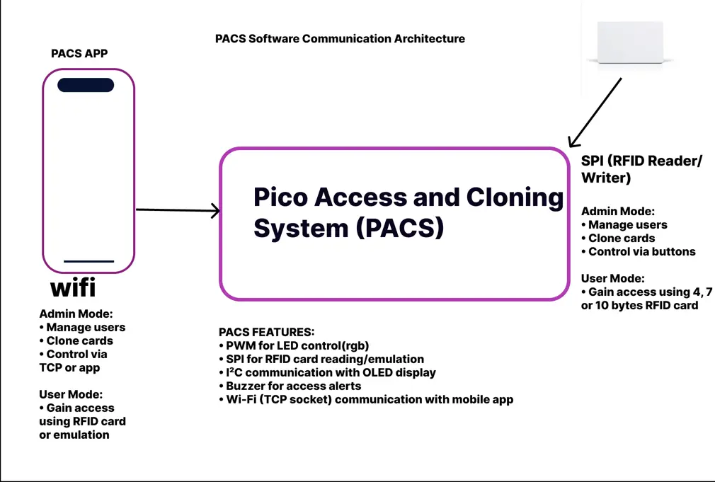
- Designed the overall PACS software architecture.
- Tested each hardware component individually using dedicated software (buzzer, LED, OLED, RFID).
- Integrated all components into a unified embedded software application.
- Developed the PACS mobile application in Flutter, with support for:
- Reading RFID cards,
- Emulating card behavior,
- Communicating with the PACS system over the internet (TCP).
- Performed full system testing, ensuring reliable interaction between the mobile app and the embedded PACS system.
Hardware
Raspberry Pi Pico 2W
- Usage: Main controller
- Function: Processes all logic and manages peripherals
RC522 RFID Module
- Usage: Card reader
- Function: Reads/writes RFID card UIDs
5V Relay Module
- Usage: Lock controller
- Function: Switches 12V solenoid circuit
12V Solenoid Lock
- Usage: Door lock
- Function: Physically secures entry point
SSD1306 OLED Display
- Usage: User interface
- Function: Shows system status/messages
Active Buzzer
- Usage: Audio feedback
- Function: Signals operations/errors
RGB LEDs
- Usage: Visual indicators
- Function:
- Green: Access granted
- Red: Access denied
- Blue: Cloning mode active
Tactile Buttons
- Usage: Mode selection
- Function: Toggle between user/admin modes
1N4007 Diode
- Usage: Circuit protection
- Function: Prevents voltage spikes
220Ω Resistors
- Usage: LED protection
- Function: Limits current to LEDs
MIFARE Classic Cards
- Usage: Test credentials
- Function: Authentication testing
Schematics

PCB Design

Bill of Materials
| Device | Usage | Price |
|---|---|---|
| Raspberry Pi Pico W | Core microcontroller | 35 RON |
| RC522 RFID Module | RFID card reading and cloning (via SPI) | 10 RON |
| Solenoid Lock | Physical locking mechanism | 34 RON |
| 5V Relay Module | Controls power to solenoid lock | 15 RON |
| Active Buzzer Module | Audio feedback for events | 1 RON |
| LEDs (RGB) | Visual feedback for status | 2 RON |
| Push Button | Mode switch (admin/user) | ~1 RON |
| 12V Duracell Battery + Holder | Power source for relay/lock | 11 RON |
| 1N4007 Diode | Flyback and polarity protection | 0.5 RON |
| 220Ω Resistors | Current limiting for LEDs | 0.76 RON |
| OLED Display | Displays messages or status | 15 RON |
| PCB Board | Board for mounting components | 15 RON |
| RFID and NFC Cards | Cards used for unlocking system(15 cards ) | 11 RON |
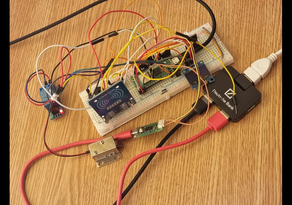
hardware connections
Software
Concepts from the laboratory that are used in the project are:
- PWM: For RGB LED control
- GPIO: For general-purpose input/output, including buttons, buzzers, and other peripherals
- I2C: For OLED display communication using SSD1306 driver
- SPI: For RC522 RFID module communication using mfrc522 driver
- Async: For network communication and task scheduling
- Wi-Fi: For wireless communication and remote access using
cyw43driver
| Library | Description | Usage |
|---|---|---|
| embassy-rp | RP2350 Hardware Abstraction Layer | Mandatory for Pico W (GPIO, SPI, I2C, PWM) |
| cyw43 | CYW43439 Wi-Fi driver for Pico W | Required for Wi-Fi connectivity |
| embassy-net | Async TCP/IP networking stack | Enables TCP socket communication |
| embassy-time | Async timers and durations | Used for task scheduling and delays |
| embassy-executor | Async runtime for embedded systems | Runs async tasks |
| embassy-sync | Async synchronization primitives (Mutex, Channels) | Thread-safe sharing between tasks |
| heapless | Stack-allocated collections (no_std) | Stores UIDs in Vec without dynamic allocation |
| defmt + defmt-rtt | Lightweight logging over RTT | Efficient debugging with minimal overhead |
| panic-probe | Crash logging with defmt integration | Graceful panic handling during development |
| mfrc522 | MFRC522 RFID reader driver | Communicates with RC522 over SPI |
| embedded-hal-bus | Shared-bus wrapper for embedded-hal devices | Provides ExclusiveDevice for safe SPI access |
| embedded-graphics | 2D drawing library for embedded displays | Renders text and graphics on OLED |
| ssd1306 | I2C/SPI driver for SSD1306 OLED displays | Interfaces with the OLED screen |
| embedded-io-async | Async I/O traits | Async write to network or displays |
| static-cell | Safe static memory initializer | Used for globally safe singleton allocations |