Blackjack Game
Using the Raspberry Pi Pico W to automate the logic for a Blackjack game
Author: Iacobescu Cristian Mario
GitHub Project Link: https://github.com/UPB-FILS-MA/project-MarioMario7.git
Description
This project facilitates a Blackjack game that allows the 'dealer' to use a barcode scanner to input the cards. The project will involve programming the Raspberry Pi Pico W to manage the game logic, display the game interface, and interact with the barcode scanner to read the cards. There are also different behaviors that correspond to different events and game states.
The choices for the players will be made using a simple web interface, and communication between the server and the Pico-side logic will be established via socket communication, utilizing the Pico's integrated Wi-Fi module.
Motivation
What pushed me to choose this project was that, while observing a similar approach bring used to facilitate online Blackjack games, I was struck by the innate simplicity of the setup and the use of relatively inexpensive parts being used by multi-million-dollar companies worldwide on a day-to-day basis.
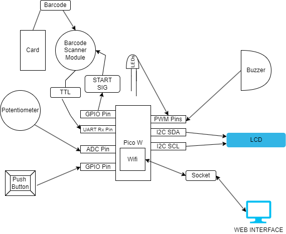
Architecture
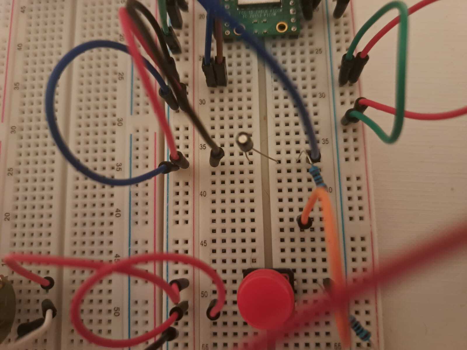
- Raspberry Pi Pico: Used for handling the game logic, controlling the scanner, LEDs, LCD and buzzer. Also for communicating with the server trough the sockets.
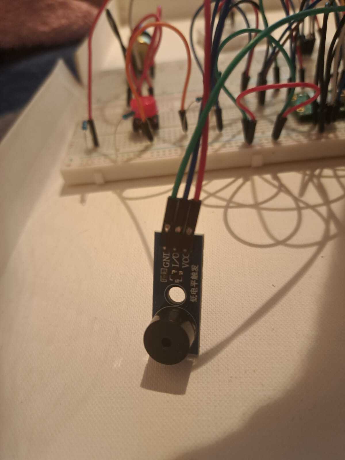
- Passive Buzzer : Reacts to varying game events.
- RGB LEDs : Reacts to game events / Used to show where the next card should be placed (Player/Dealer).
- Barcode Scanner Module(+ RS232 -> TTL Adaptor) : Barcodes are scanned from the cards and are then used for the game logic, if the serial sent matches one of the ones stored in the dictionary and if it wasn't previously scanned in the current round (if any of the conditions are false, it will create a placeholder card object and suspend the game until a rescan is done successfully). The adaptor is needed as the Raspberry Pi Pico W doesn't support RS232 communication. We will use Transistor-To-Transistor Logic communication through the Pico's pins that support UART communication.
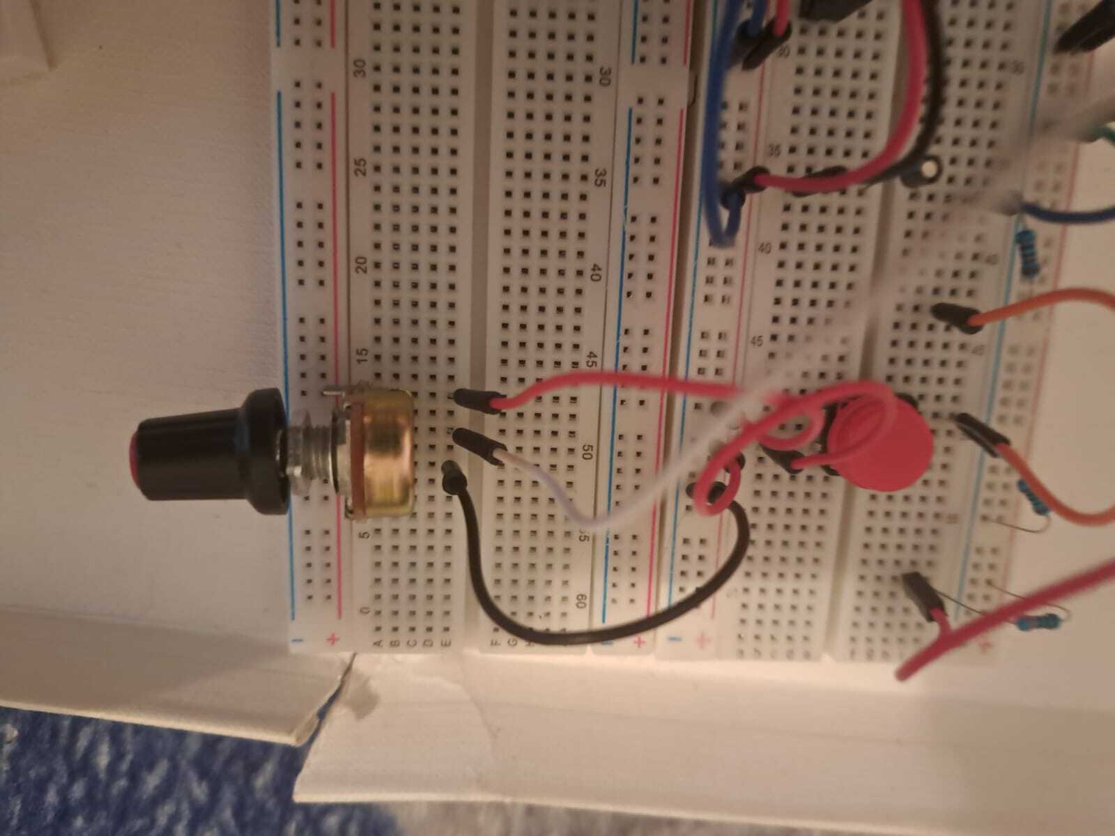
- Linear Potentiometer + Push Button: The potentiometer is used for choosing the bet for the new round, and the push button is used to confirm the bet and start the round.
- 16x02 LCD: Used to display relevant information for pre/current/post game states.
- Website Interface : Allows the user to select the choices for the game (Insurance, Hit, Stand, Double Down, Split). Communicating with the Pico trough the sockets of the web server to send/recieve information relevant to the current round. The server will run on a local machine, no connections other than the Pico are inteded.
Log
Week 6 - 12 May
This period marks the start of the project, where the task at hand was to define a clear outline and path going forward. The LCD was the first major component to be tested.
After thoroughly reading the datasheet, I figured out what commands to send for each instruction using the I2C module. However, as I would soon find out, the commands after turning the display on, making the cursor appear on the screen, and making the cursor blink were not doing anything. This led me to try to send the commands 4 bits at a time instead of 8, but after that did not work, I pinned the problem down to a timing issue for the commands. After a lengthy process of trial and error, I still could not determine the correct timing needed for the commands that wrote characters to the screen. This, of course, led to using a Rust library to operate the LCD, which massively simplified the process for anything related to the display.
Next on the list was choosing the structure of the Blackjack game logic. The paradigm that made the most sense for this project was Object-Oriented Programming, as its rules and fundamental concepts fit a Blackjack game perfectly. A deck is comprised of cards that have a suit and a rank, which are used to add to the player’s or dealer's score, then, this score is then used to determine the winner of a round, etc.
With this objective in mind, I set out to create the mold for the Pico-side Blackjack logic. This was done quite quickly and allowed me to move on to the next part of the project, and the most important: the scanner, which will be taken care of in the next week or so.
Week 7 - 19 May
Up until this point, I had completed the basic structure of the blackjack game on the software side and tested the LCD. During this period, my main goal was setting up the scanner module and writing the code needed to operate it. At first, the setup seemed to be more difficult than expected: the blocking_read function was returning a BREAK error.
After some research, I quickly found out that this error signifies that the line stays in a low state for longer than expected, which led me to find out that the baud rate in the default UART config did not match that of my scanner. Embassy uses the default baud rate of 115200 and the scanner uses 9600. This issue was solved relatively quickly and the setup was ready to go since the scanner uses 8 data bits, one stop bit, and no parity (same as the default config in Embassy).
After this, a lot more information was revealed about the scanner (which unfortunately was not available in the datasheet as the datasheet itself doesn't exist): it turns itself off automatically after approximately 4 seconds as a form of protection, as it heats up very quickly, it uses UTF-8 encoding, the stop bit is 13 (which in ASCII is CARRIAGE_RETURN - represents the action of moving the cursor or print head back to the beginning of a line). This all led to a successful integration of the scanner into the project and after finishing the rest of the small hardware setup, only the blackjack logic and the socket communication + website are left for the upcoming weeks.
Week 20 - 26 May
For the last week of this project, as was previously mentioned the blackjack logic and the socket communication + website were left. The "only" in my previous log was underestimating the work put behind this 3 parts of the project massively.
The first and easiest part was the webiste that runs on an HTTP Node server, it was done very minimaslistically, just focusing on the bare minimum: the buttons for the player choices, which was, of course a statement regarding my preference of the aforementioned style, and definitely not because i only had 3 days to finish the project. Anyhow, the network configuration is as follows:
- We have an HTTP server for the website on port 3001 (used express to handle the POST requests from the server)
- An UDP server running on port 3000 ( used dgram since UDP uses datagram packets/sockets)
- Pico is binded on port 3002
The webiste send a POST request for the player choices with the buttons, wrapped in a JSON which is handled server-side and has its data passed to the UDP server, which in turn, will send it to the pico on port 3002, in the form of bytes passed in a buffer.
Then the Pico hadles logic as per the rules of the Blackjack game, and requests to recieve data from the server only happen when needed.
The 1st problem encountered was that, due to the non-static ipv4 configuration of my laptop for the wifi, i had to change the ip on wich the server runs on, everytime my wifi closed/reopened, anf sometimes, on different IPs the communciation to the Pico would fail no matter what, the solution of "turn it off and back on again" eventually worked the 3rd time.
Another problem was that, the bigger the code, the less likely the logger was to display aything in the console. This lead to a lot of confusion for me, as i thoyght that i had a problem with my code's logic ,but after trying to us ethe LCD to print when the logger would stop working theis issue would vanish quickly.
Other than these, I haven't had any major roadblocks and were able to complete the software part after many and many hours of coding and testing.
Hardware
We will use a Raspberry Pi Pico W as the microcontroller. A potentiometer is used for getting the player's 'bet', and a push button used to confirm the bet (an RC Filter will be used to ensure no switch bounce happens).
The main piece of hardware for this project is the barcode scanner, which scans the barcodes from the playing cards and facilitates a way to connect the real-life events to the microcontroller for handling the logic behind the game. It sends the barcodes encoded using the UTF-8 encoding standard.
An adaptor (RS232 -> TTL) is needed for the scanner since it uses RS232 communication, which is not supported by the Pico. We also use an LCD to display relevant information, and the RGB LEDs and buzzer to react to game events.
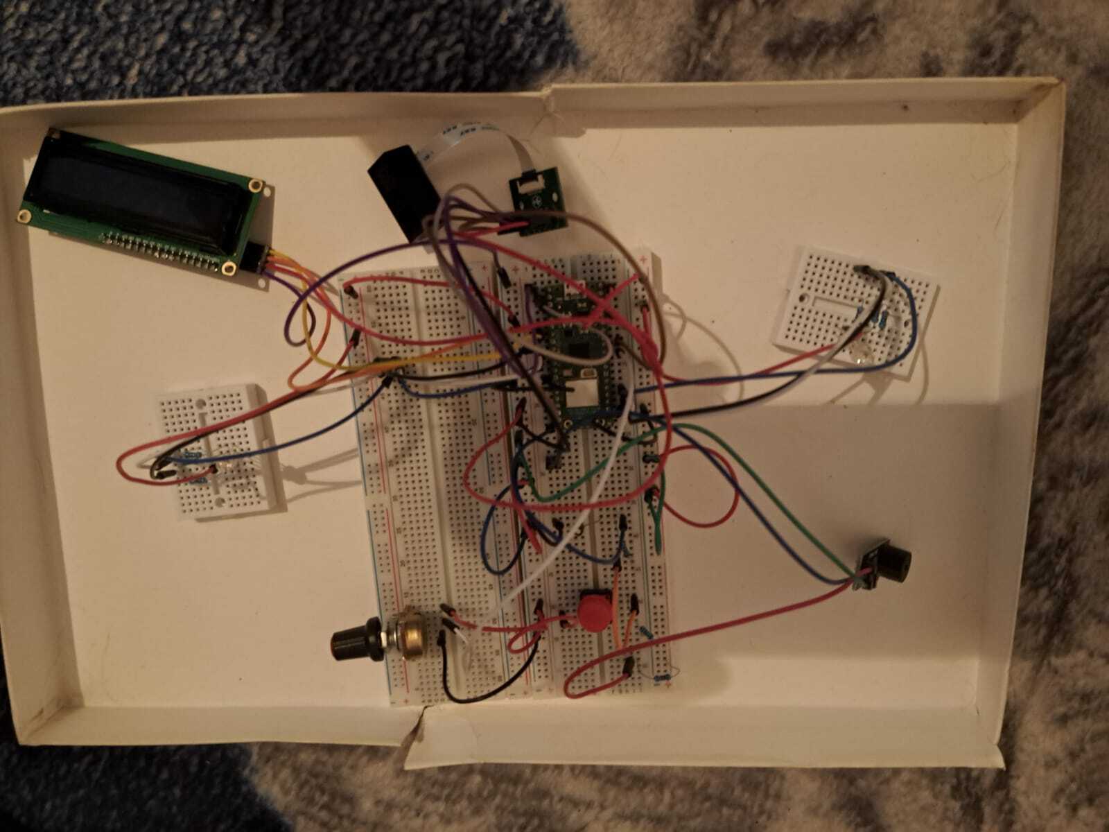
Bird's Eye View
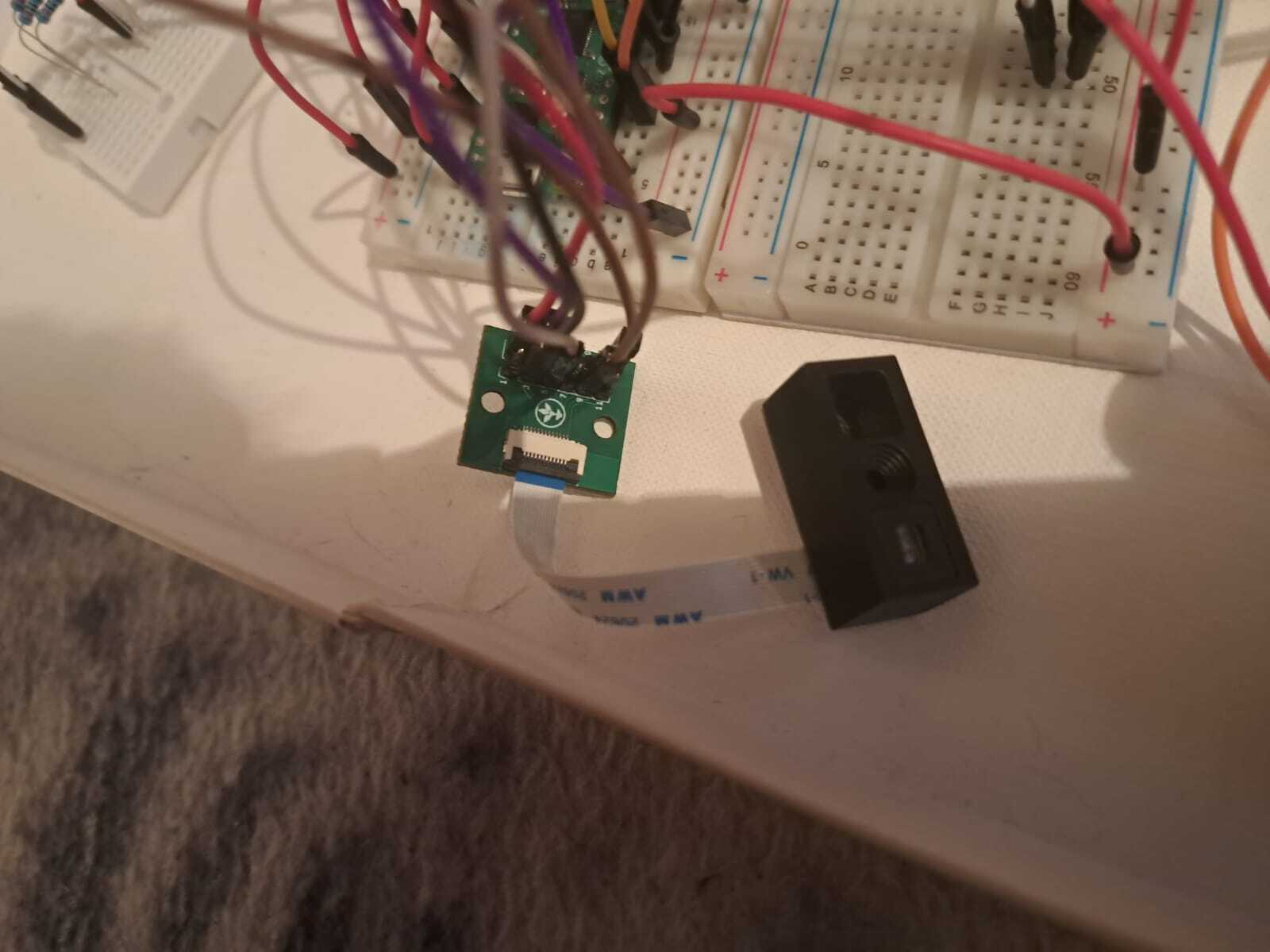
Scanner
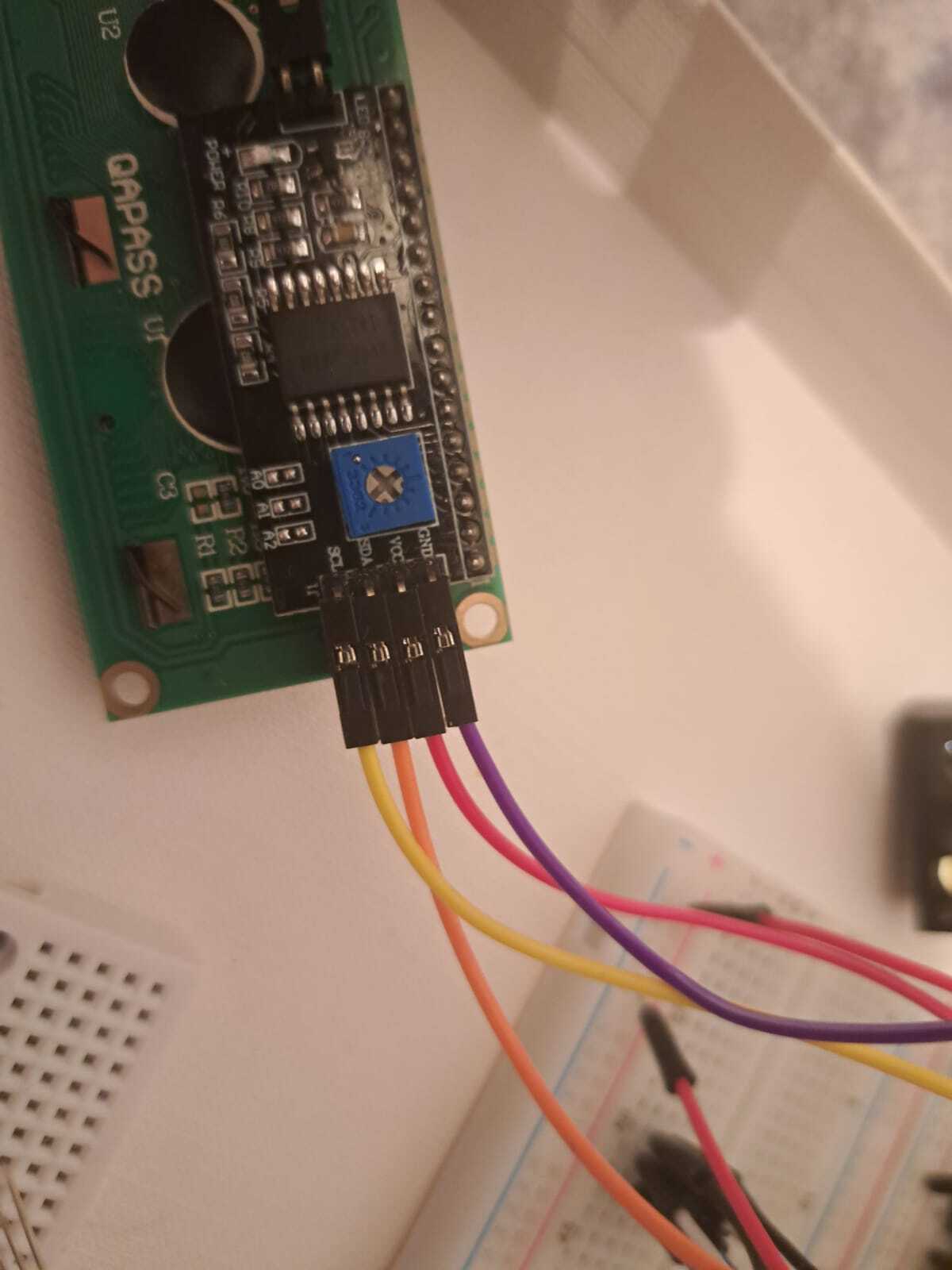
LCD
Buzzer
Potentiometer
Push Button with physical pull-down resistor
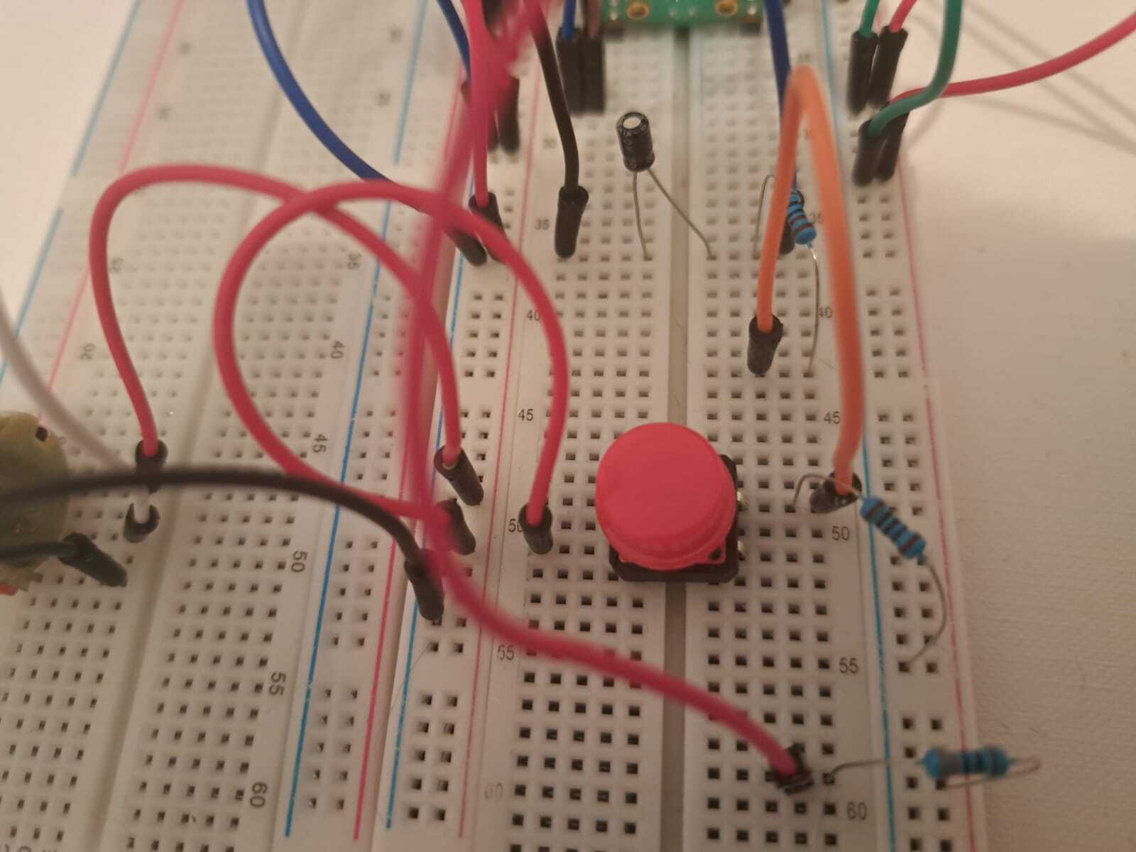
Resistive Capacitive Filter
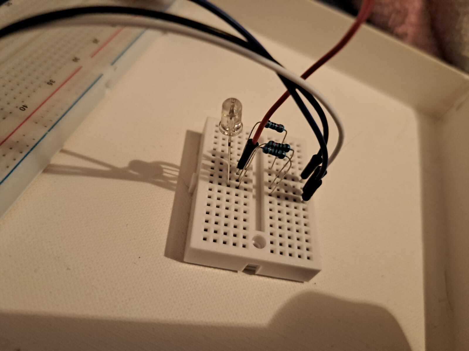
RGB LEDs
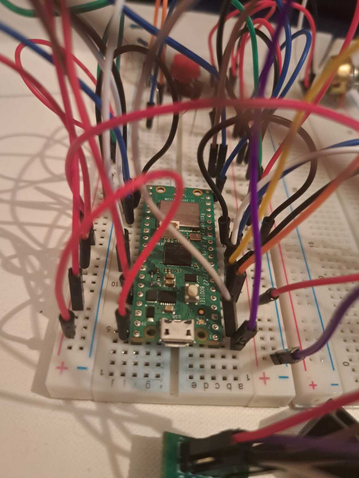
Pico Close-Up
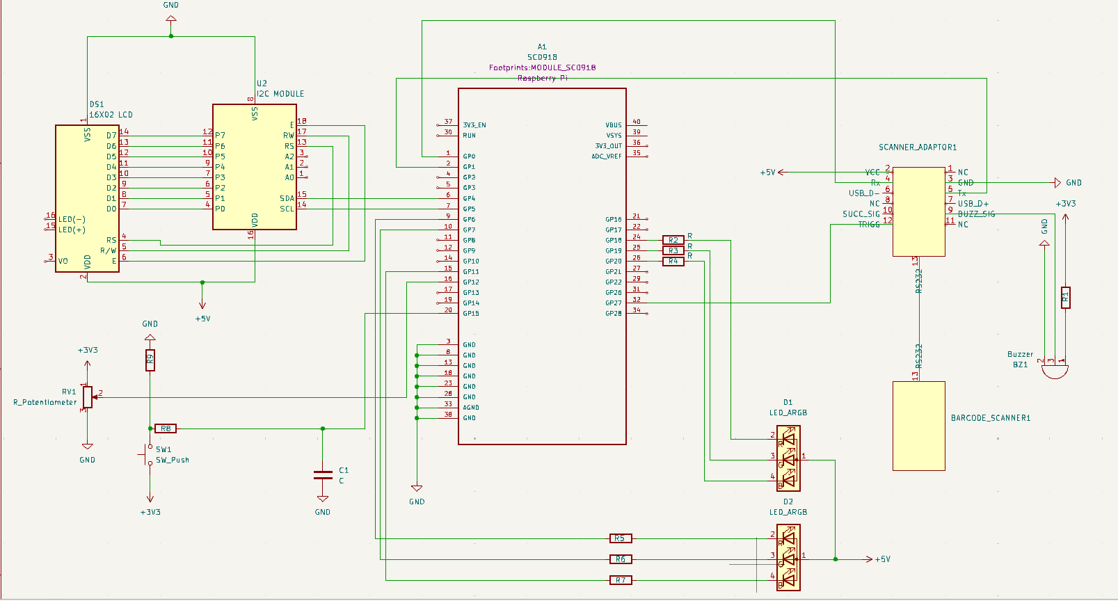
Schematics
Bill of Materials
| Device | Usage | Price |
|---|---|---|
| Raspberry Pi Pico W | The microcontroller | 35 RON |
| Breadboard830 | The main breadboard | 10 RON |
| Linear Potentiometer | Set the bet | 2.5 RON |
| Push Button | Confirm Bet | 0.50 RON |
| RGB LED | Display player turn and game state | 2.50 x 4 RON |
| Barcode Scanner | Scan the QR Codes on the cards | 80 RON |
| RS232 -> TTL Adaptor | Connect the scanner module to the pico | 6 RON |
| Buzzer Module (Passive) | React to game events | 4 RON |
| Mini Breadboard | Breadboard for the LEDs | 3 x 4 RON |
| 1602 LCD Screen with I2C Interface | Display game details | 15 RON |
| Capacitor (0.1 uF) | Debounce button to avoid unwanted input | 0.25 RON |
| Jumper wires | Connect components | 20 RON |
| Male-Female Cables | Connect components | 5 RON |
| Female-Female Cables | Connect components | 15 RON |
| Resistors | Regulates voltage for components | 22 RON |
Software
| Library | Description | Usage |
|---|---|---|
| heapless | Data structure library | Used for String vectors |
| embassy_rp | Embassy Hardware Abstraction Layer (HAL) for the Raspberry Pi RP2040 microcontroller | Used to program the Pico |
| embassy_sync | Synchronization primitives and data structures with async support | Used for communicating through different tasks |
| embassy-executor | An async/await executor designed for embedded usage | Used for task execution |
| ag_lcd | Library that allows developers to control a HITACHI HD44780 LCD screen with one or two 16-character lines | Used to operate the LCD |
| port_expander | Abstraction for I2C port-expanders | Used for handling the Pcf8574 I/O Expander |
| embassy_time | Timekeeping, delays and timeouts. | Used for delays |
| byte_slice_cast | Cast bytes slices from/to slices of built-in fundamental numeric types | Used for byte handling |
| cyw43_pio | RP2040 PIO driver for the SPI used in the Pico W. | Used for controlling the wifi chip |
| embassy_futures | Utilities for working with futures. | Used for handling futures |
| embassy_net | Async network stack. | Used for communciating through WiFi |
| static_cell | Statically allocated, initialized at runtime cell. | Used for reservig memory at compile time for a value, but initialize it at runtime, and get a 'static reference to it. |