Smart Fan
Displays room temp/pressure, auto-activates at thresholds.
Author: Cristea Ioana-Maria
GitHub Project Link: https://github.com/UPB-FILS-MA/project-Ella23411
Description
A fan that monitors and displays the temperature and pressure in the room on a LCD screen, then activates the fan after a certain threshold :
-
The system utilizes a sensor to detect both temperature and pressure.
-
The LCD screen showcases the temperature and pressure readings.
-
The fan is triggered once the threshold is exceeded.
-
A buzzer is activated once the threshold is surpassed.
-
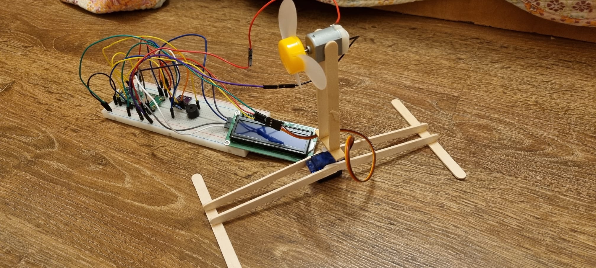
After the threshold is exceeded, the fan's arm oscillates from side to side.
Motivation
This project holds a special significance for me because it allowed me to bridge the gap between theory and practice. Throughout my time in the laboratory, I gained valuable insights into the fundamentals of electronics and programming. However, there were certain aspects that I didn't have the chance to explore fully.
By undertaking the development of a smart fan, I saw an opportunity to not only apply the knowledge I acquired in the lab but also to expand my skill set in areas that were previously uncharted territory for me. Combining hardware with software was a challenge I eagerly embraced, and through this project, I gained invaluable hands-on experience in integrating the two seamlessly.
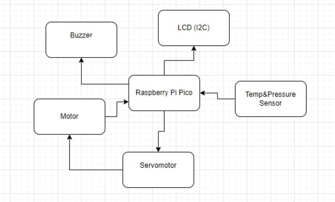
Architecture
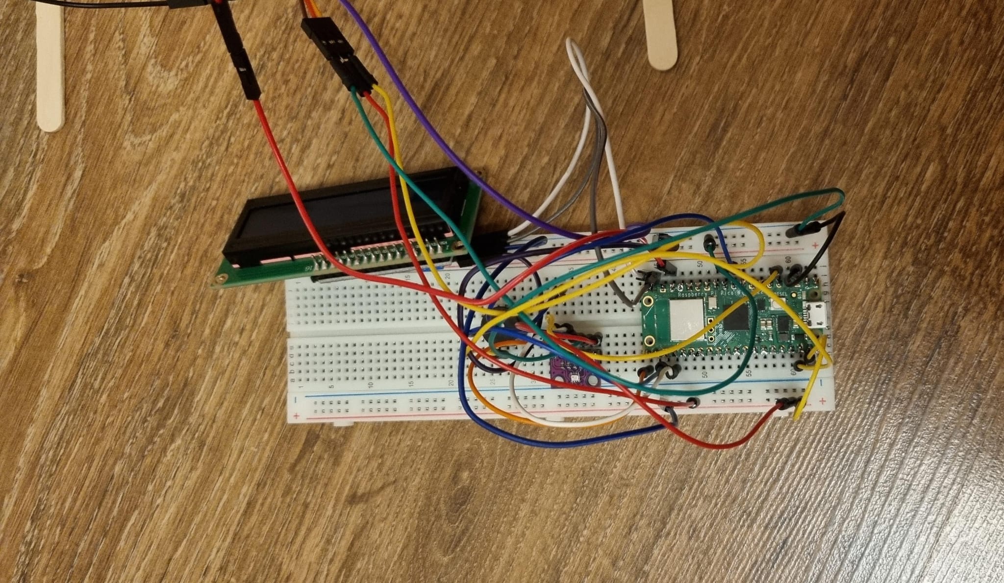
The Raspberry Pi Pico serves as the central control unit, directing and managing all other components utilized within the project.
The LCD serves as an interface for showcasing the sensor readings, it is connected to the Pico through I2C
The servomotor is connected to an improvised arm, allowing the fan to rotate 90° in either direction.
The buzzer, when the temperature threshold is surpassed, emits an alarm, acting as an alert mechanism.
The pressure and temperature sensor detects changes in temperature and pressure, supplying input to the Pico.
A DC Motor that controls the fan
Log
Week 6 - 12 May
I uploaded the necessary project documentation, making sure everything was in order. Then, I began working on the schematics, carefully mapping out the design. Additionally, I started developing some of the software. Each step brought the project closer to realization.
Week 7 - 19 May
In the following week, I completed the hardware and assembled the makeshift arm, which presented a few challenges. However, I managed to resolve them successfully. Additionally, I made further progress on the software development.
Week 20 - 26 May
In the final week, I successfully completed the software development and thoroughly tested its functionality to ensure it met all project requirements. Additionally, I finalized the hardware components, ensuring they were perfectly integrated with the software. The design was also polished to achieve a cohesive and professional look.
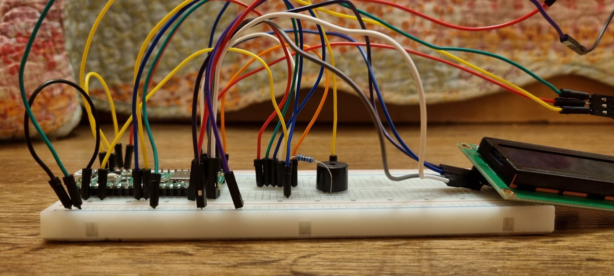
Hardware
- Raspberry Pi Pico:
- Purpose: Controls all components.
- Function: Acts as the main controller, coordinating the operations of sensors, motors, buzzers, and the LCD display.
- Temperature and Pressure Sensor:
- Purpose: Detects changes in temperature and pressure.
- Function: Continuously monitors the environment and sends data regarding temperature and pressure to the Raspberry Pi Pico.
- Active Buzzer:
- Purpose: Emits sound alerts.
- Function: Activates when the temperature exceeds the preset threshold, providing an audible warning.
- DC Motor with Fan:
- Purpose: Provides cooling.
- Function: Activates when the temperature exceeds the preset threshold, turning on the fan to help reduce temperature.
- Servomotor with Makeshift Arm:
- Purpose: Performs mechanical action for signaling or other purposes.
- Function: Activates when the temperature exceeds the preset threshold, moving the arm 90 degrees to each side.
- LCD Display:
- Purpose: Displays real-time data.
- Function: Shows the current temperature and pressure readings, allowing for easy monitoring of environmental changes.
Hardware Overview:
- The Raspberry Pi Pico controls and coordinates all components.
- The Temperature and Pressure Sensor continuously monitors the environment.
- When the temperature exceeds the set threshold:
- The Active Buzzer sounds an alert.
- The DC Motor activates the fan to cool the area.
- The Servomotor moves the makeshift arm 90 degrees to each side as a physical signal.
- The LCD Display provides real-time updates of temperature and pressure, ensuring that the changes are visible and trackable.
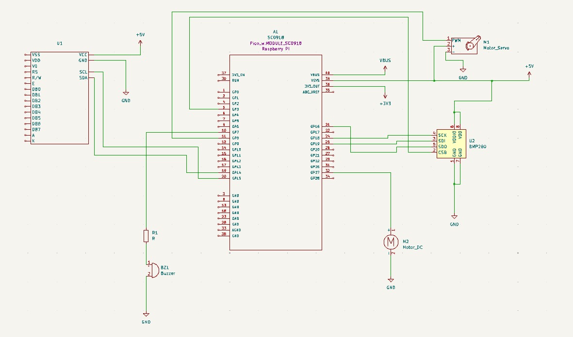
Schematics
Bill of Materials
| Device | Usage | Price |
|---|---|---|
| Rapspberry Pi Pico W | The microcontroller | 35 RON |
| BMP280 | Temperature Sensor | 8,49 RON |
| Active Buzzer | Active Buzzer | 1,49 RON |
| LCD Display | LCD Display | 30 RON |
| DC Motor | DC Motor | 3,50 RON |
| Servomotor | Servomotor | 14 RON |
Software
| Library | Description | Usage |
|---|---|---|
| ag-lcd | Display Library | Used for I2C LCD Display |
| embassy-rp | RP2040 Peripherals | Used for accessing the peripherals |
| embassy-time | Time Library | Used for Timeouts and Delays |
| Heapless | String Library | Used to making strings for writiing to the lcd |