02 - Memory Mapped IO & GPIO
The purpose of this lab is to understand how to start developing in Rust for the RP2040 MCU. The lab presents three examples:
- bare metal development - writing directly to registers, actually writing a driver
- platform access crate (PAC) - using an automatically generated crate from the MCUs SVD file, actually writing a driver, but with some kind of automation
- embassy-rs - using the Rust standard
embedded-halimplemented by the Embassy-rs framework.
The example of this lab is to blink an LED at a certain time interval.
Resources
- Raspberry Pi Ltd, RP2040 Datasheet
- Raspberry Pi Ltd, Raspberry Pi Pico Datasheet
- Raspberry Pi Ltd, Raspberry Pi Pico W Datasheet
What is GPIO?
General-Purpose Input/Output, or GPIO, is an essential part of embedded systems that serves as a vital conduit between microcontrollers and microprocessors and the outside world. A microcontroller or microprocessor's group of pins that can each be set to operate as an input or an output is referred to as GPIO. The purpose of these pins is to interface external components, including actuators, displays, sensors, and other devices, so that the embedded system may communicate with its surroundings. Standardised communication protocols like SPI, I2C, PCM, PWM, and serial communication may be directly supported by some GPIO pins. There are two varieties of GPIO pins: digital and analog.
Configuring GPIO Pins
GPIO pins can be used as outputs (LEDs, motors, buzzers) or as inputs (buttons, sensors).
The R02040 has three peripherals that control the GPIO pins:
- Pads - control the actual physical pin or pad that the processor has outside. This control the electrical parameters, like maximum current or pull up and pull down resistors
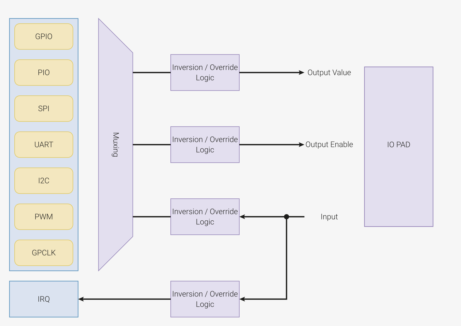
- IO Bank0 - connects and multiplexes the peripheral's pins to the output pads. Several peripherals use the same output pad to communicate with the exterior. For example, in the image below,
GPIO0can be used either for:SIO- theGPIOfunctionSPI_RX- the receive pin for theSPIperipheralI2C0_SDA- the data pin for theI2C0peripheralUART0_TX- the transmit pin for theUART0(serial port 0) peripheral
- SIO - that controls the interior MCU's pins. This is the peripheral that developers use to read and write the value of the pins.

Every pin of the MCU can perform multiple functions. Several peripherals need to use input and output pins. It is the role of the IO Bank0 to multiplex and connect the peripherals to the pins.
Hardware access
There are 3 different ways in which the hardware the Raspberry Pi Pico can be used:
- Embassy-rs framework, with the Embedded HAL implementation
- Platform Access Crate (PAC)
- Bare metal
Embedded HAL Implementation
The bare metal and PAC require a lot of time and effort to develop applications.
The Rust Embedded devices Working Group has designed a set of standard traits (interfaces) for interacting with an MCU. This is called the Embedded Hardware Abstraction Layer, or shortly Embedded HAL. The main purpose is to define a common hardware interface that frameworks, libraries and operating systems can build upon. Regardless of what MCUs the device is using, the upper level software should be as portable as possible.
There are several crates and frameworks that implement the Embedded HAL traits for the RP2040 MCU.
- rp2040_hal crate, implements just the embedded HAL traits, it is the bare minimum for developing RP2040 applications
- embassy-rp crate implements the Embedded HAL for RP2040 that is used with the embassy-rs framework
Embassy-rs framework
Embassy-rs is a full fledged embedded framework for Rust embedded development. Besides the implementation of the embedded HAL for different MCUs (RP2040 included), embassy-rs provides several functions like timers, BLE and network communication.

The crates used by Embassy-rs and their mapping are shown in the table bellow.
| Crate | Position |
|---|---|
embassy-executor | Framework |
smoltcp, defmt | Libraries |
embassy-net, embassy-time, embassy-usb, embassy-usb-logger | Framework Driver |
embassy-usb-driver, embassy-time-driver | Embassy HAL (API) |
cyw43, cyw43-pio | Driver (WiFi) |
embedded-hal, embedded-hal-async | Rust Embedded HAL (Standard) |
embassy_rp | HAL Implementation |
cortex-m, cortex-m-rt | μ-architecture crates |
rp_pac | Platform Access Crate |
The name Embassy-rs is derived form Embedded Asynchronous Rust.
Entry
Embassy-rs is a framework built on top of cortex-m-rt and provides its own method of defining
the entrypoint and bootloader.
use embassy_executor::Spawner;

#[embassy_executor::main]
async fn main(_spawner: Spawner) {
    let peripherals = embassy_rp::init(Default::default());
}
The embassy_rp::init function takes care of the peripheral initialization so that developers can jump
right in and use them.
Embassy-rs is designed to work in an asynchronous way and this is why the main function is defined as async. For the time being, just take it as a must and ignore it.
Configure GPIO Output
Embassy-rs provides one single function that returns the GPIO Output pin and hides the configuration
details from developers.
The pin variable implements the embadded HAL OutputPin trait.
use gpio::{Level, Output};

// initialize PIN_n (replace n with a number) and set its
// default value to LOW (0)
let mut pin = Output::new(peripherals.PIN_n, Level::Low);

// set the pin value to HIGH (1)
pin.set_high();

// set the pin value to LOW (0)
pin.set_low();
While the device initialization is specific to every hardware device (the example uses the
embassy_rp crate that is for RP2040), the pin initialization and usage is portable. It
uses the same code, regardless of the MCU used.
Configure GPIO Input
Using a pin as input is very similar to using it as output.
use gpio::{Input, Pull};

let pin = Input::new(peripherals.PIN_n, Pull::Up);

if pin.is_high() {
    // Do something if the pin value is HIGH (1)
} else {
    // Do something if the pin value if LOW (0)
}
For a correct use of the buttons, use pull-up, pull-down resistors depending on the mode of operation of the button. Check 01 - Hardware Introduction
Waiting
Embassy-rs provides support for suspending the execution of the software for an amount of time. It uses
the Timer structure from the
embassy_time crate.
// suspend the execution for a period of time
use embassy_time::Timer;

Timer::after_secs(1).await;
If the MCU provides timers, the Embassy framework will use them to suspend the software. This is very efficient.
Platform Access Crate (PAC)
A mid level way of developing in Rust for MCUs are the platform access crates (PAC). These crates are automatically generated from the System View Description (SVD) files.
Using rust2svd, developers can automatically generate a crate that provides access functions to the MCUs registers. This provides a significant improvement, as developers do not have to write manually the register addresses.
One of the PAC crates for the RP2040 MCU is rp2040-pac.
The PAC crate does not provide any means of initializing the MCU, so the entry point is still
defined by the cortex-m-rt crate, just as it is for bare metal. Bare metal will be discussed later in the lab.
Similarly, the PAC crate does not provide any sleep function.
This section presents only the differences between bare metal and PAC. The PAC mode of writing embedded software is very similar to bare metal, just that register access is made easier.
The RP2040 (ARM Cortex-M0+) MCU uses Memory Mapped Input Output (MMIO). This means that the peripheral's registers are mapped into the address space (in normal words, in the memory). Reading and writing data from and to these registers is done by memory reads and writes.
Blinking an LED in PAC or bare metal programming means following these steps:
- Ask the rust compiler not to use the
stdlibrary, as it depends on the operating system - Write a
mainfunction and instruct the MCU to call it at startup (reset) - Configure the Single Cycle IO (SIO) peripheral to set a pin as output
- Enable the IO Bank0 peripheral of the RP2040
- Configure the IO Bank0 peripheral so that it sets a certain pin as output
- Toggle the pin's value through the SIO's registers
- Wait for an amount of time
- Loop through steps 6 and 7
no-std
As the code written runs on an MCU without any framework or operating system,
the Rust compiler cannot rely on the std library. The two macros directives
ask the compiler not to link the std library and not to expect main
function.
#![no_main]
#![no_std]
The bare metal code has to start with these two directives.
Bootloader
The RP2040 has a piece of software written in an internal ROM memory that is loaded when the MCU boots. This looks at the first 256 bytes of the Flash memory to understand how it needs to start the MCU.
While the ROM bootloader is rather small, its functionality is very similar to the PC's BIOS boot sequence.
The RP2040's datasheet explains the boot process. This is not very straight forward, and writing this
information requires a digital signature. The rp2040-boot crate provides the bootloader information
for booting with the cortex-m-rt crate.
Adding the following code to the Rust includes the bootloader.
#[link_section = ".boot_loader"]
#[used]
pub static BOOT_LOADER: [u8; 256] = rp2040_boot2::BOOT_LOADER_W25Q080;
Entry
For this lab, we will use the cortex-m-rt crate. As the starting code for an MCU is usually processor
and vendor dependent, this crate allows developers to get started a little faster. It implements the bare minimum
initialization code and provides a macro called entry that developers can use to select the startup (main)
function.
The entry macro is used by Embassy through the embassy_executor::main macro that sets the main function as the startup point and defines the correct bootloader.
When an error occurs, Rust calls the panic function. When using the std library, the panic function is
already defined. It prints the error and usually unwinds the stack. When using core, it is the developer's
job to define a panic function. In the case of bare metal development, the simplest panic function is
one that loops indefinitely, preventing the MCU form executing code.
use core::panic::PanicInfo;

use cortex_m_rt::entry;

// the `entry` macro sets up this function
// as the function that the MCU calls at
// startup
#[entry]
fn main() -> ! {
    // the `main` function is not allows to return
    loop { }
}

// rust uses panics when an error occurs
// as this is bare metal, we have to define
// the panic function that rust calls
#[panic_handler]
fn panic(_info: &PanicInfo) -> ! {
    // if an error occurs, we simply loop around
    // to prevent the MCU from executing
    // anything
    loop {}
}
In PAC or bare metal mode, the MCU does not run any framework or operating system, it just runs the developers bare metal code. This is why main function is not allowed to return, it loops forever. There is no system to which the function
could return control.
One of the first lines of the main function is getting a reference to all the
peripherals.
use rp2040_pac::Peripherals;

#[entry]
fn main() -> ! {
    // get a reference to all the peripherals
    let peripherals = Peripherals::take().unwrap();

    loop { }
}
In Embassy, the main function does not have to loop indefinitely, it is allowed to return, as it runs within the embassy-rs framework.
Configuring the SIO
In bare metal and PAC modes, developers have to manually initialize the IO Bank0 and SIO peripherals.
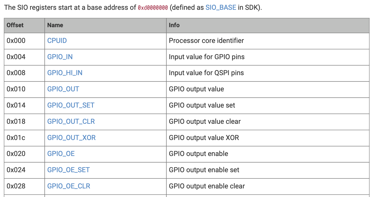
The GPIO pins are configured using the MCU's SIO registers. Each pin is configured by setting or clearing the corresponding bit of several registers. Below is a table with the memory addresses of the SIO registers.
The PAC crate provides the SIO peripheral, which in turn provides a function for
each one of its registers. It fully hides the actual address of the registers.
let sio = peripherals.SIO;

// set the `pin` pin as output
sio.gpio_oe_set().write(|w| unsafe { w.bits(1 << pin) });

// set the `pin` to value `0`
sio.gpio_out_clr().write(|w| unsafe { w.bits(1 << pin) })

// set the `pin` to value `1`
sio.gpio_out_set().write(|w| unsafe { w.bits(1 << pin) })
Configuring the IO Bank0
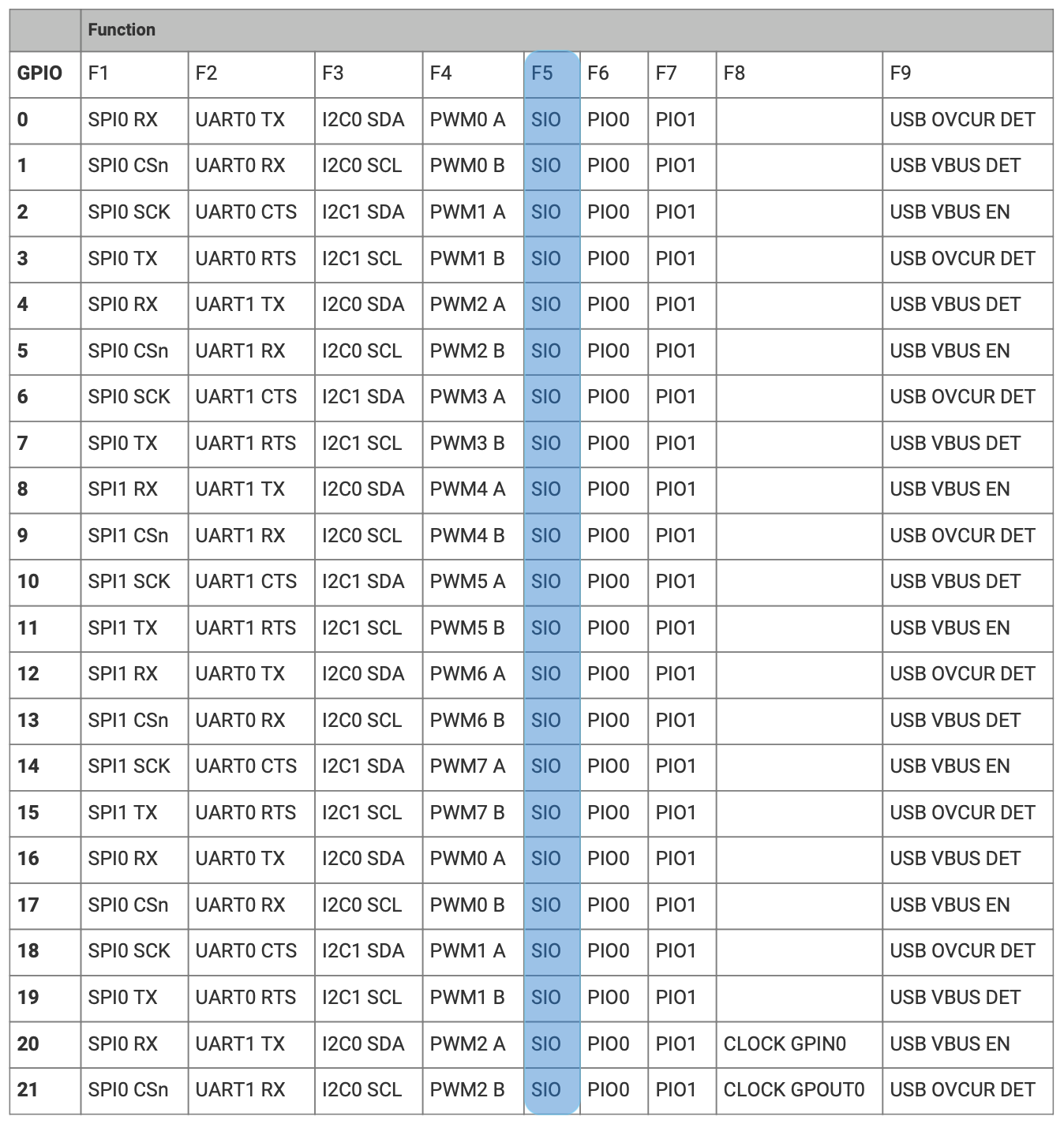
GPIO pins can be configured for several functionalities, they can be used as GPIO pins or can also be used by certain peripherals, usually those that implement communication protocols. The RP2040's IO Bank0 peripherals performs this multiplexing.
The following table provides all the functions that each pin can have.
Enable the IO Bank0
When the RP2040 starts, the IO Bank0 peripheral is disabled. To enable it, developers have to
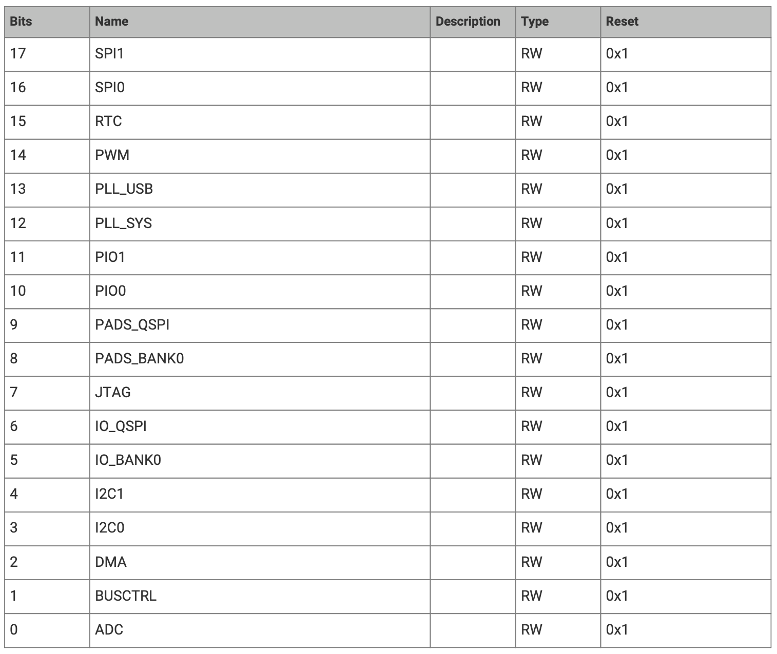
use the Reset's peripheral RESET register.
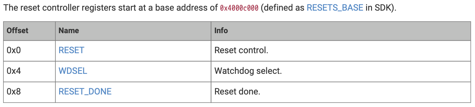
The fields of the RESET register. To enable IO Bank0, developers have to write
a 0 in the IO_BANK0 fields. By default, this field has the value 1, which means that
`IO Bank0 is disabled.
To verify that the IO Bank0 peripheral has been enabled, developers have to check the field
IO_BANK0 of the RESET_DONE register shown in the table bellow.
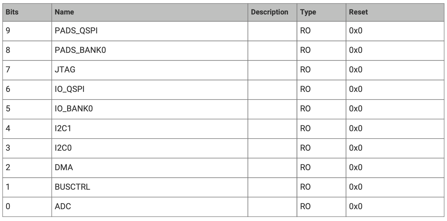
Developers might choose not to wait until the peripheral is enabled, but any writes to the peripheral's registers will most probably be ignored.
let reset = peripherals.RESETS;

reset
    .reset()
    .modify(|r, w| unsafe { w.bits(r.bits() & !(1 << 5)) });
while reset.reset_done().read().bits() & (1 << 5) == 0 {}
Configure the GPIO
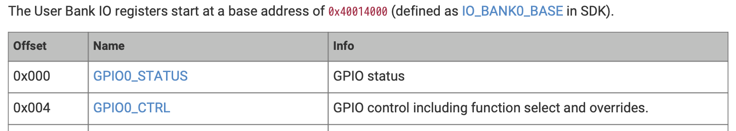
To connect the SIO peripheral to the output pins, developers have to modify the GPIOx_CTRL register.
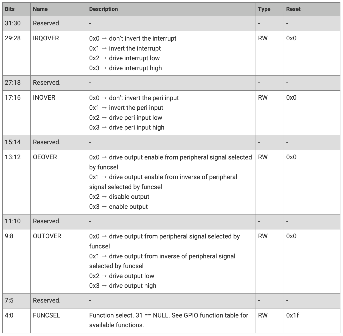
The following table shows the fields of the GPIOx_CTRL register. The fields that is of interest is FUNCSEL.
Depending on the value written there, the IO Bank0 will select a function or another. For this example,
we have to write value 5.
let io_bank0 = peripherals.IO_BANK0;

// write the value 5 to the FUNCSEL field
// Note: This actually writes the value 5 in FUNCSEL
//       and 0s in all the other field. While this
//       is fine for this example, usually a
//       read, modify, write sequence should be used
io_bank0
    .gpio(pin)
    .gpio_ctrl()
    .write(|w| unsafe { w.bits(5) });

// the correct way of doing this
io_bank0
    .gpio(pin)
    .gpio_ctrl()
    // the PAC crate provides fucntions for all the
    // register's fields
    .modify(|_, w| unsafe { w.funcsel().bits(5) });
Configuring the Pad
The Pad peripheral is responsible for the electrical setup of the pins. It can configure the the maximum output current, input pull up or pull down resistor.
The following table shows the Pads peripheral registers. Each GPIO pin has a corresponding register.
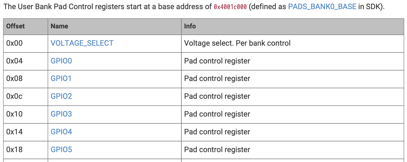
The following tables describe the GPIOx register. This register allows the configuration of several
electrical parameters.
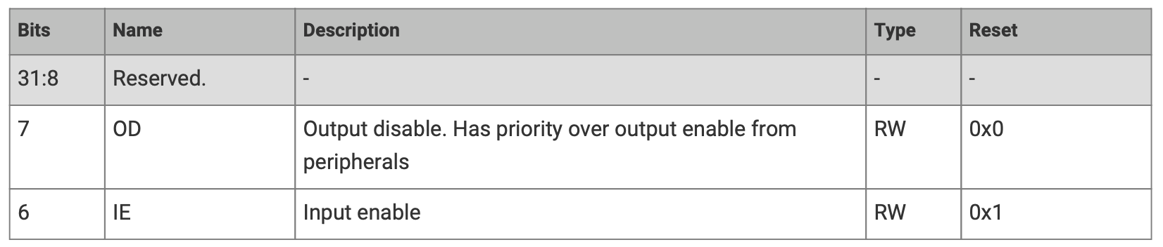
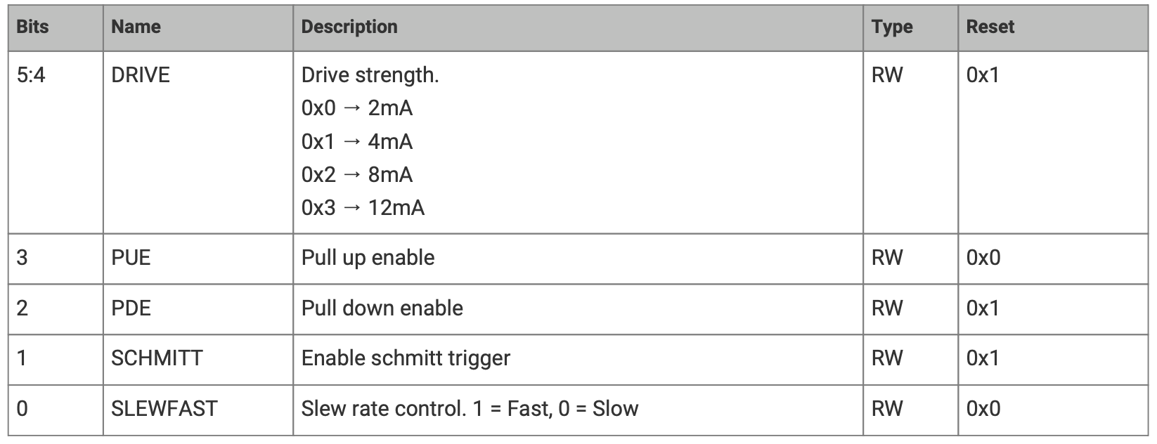
Looking at the default values, when the MCU starts, pins are configured:
| Output Enabled | Yes |
| Input Enabled | Yes |
| Maximum Output Current | 4mA |
| Pull Input Resistor | Pull Down |
| Schmidt Trigger | Yes |
| Slew Rate | Slow |
For this lab, the default values are fine, this peripheral can be considered as being properly setup.
Wait for an amount of time
When using an operating system, developers usually have a function called sleep which asks the operating system
to suspend the process for a certain amount of time. In bare metal environment, with no framework or operating system,
this is not available. The MCU timers can be used for this, but the simplest (and most inefficient) of waiting is to
loop around while doing nothing. The Arm Cortex-M processors offer the nop instruction. This asks the processor
to do nothing.
// loops around 50000 times asking the processor
// to execute the `nop` instruction that does
// nothing
for _ in 0..50000 {
    // without this `asm` here, the compiler would optimize out the loop
    asm!("nop");
}
The asm("nop") is necessary, as otherwise the compiler optimizes out the empty loop.
The question is how fast does this execute. The RP2040 starts by default using an internal 12MHz clock.
The loop itself and the range (0..50000) calculation take another 4 - 5 MCU cycles. The actual wait time
of the example is:
This approach is inefficient compared to the method used in Embassy.
Bare metal
When using bare metal, developers interact directly with the hardware devices. They are responsible for all the drivers and other components that they want to use. Mostly, bare metal development means reading and writing data from and to the MCUs and peripheral registers.
Configuring the SIO
The SIO peripheral has a base address, the address where its registers are mapped in the address space.
Each register has an offset, that represents the registers position (offset) relative to the SIO's base address.
Computing the actual address of a register means adding the base address of the peripheral with the register's offset.
e.g: GPIO_OE's address is 0xd000_0000 + 0x020 => 0xd000_0020
use core::ptr::write_volatile;

const GPIO_OE_SET: *mut u32 = 0xd000_0024 as *mut u32;
const GPIO_OUT_SET: *mut u32 = 0xd000_0014 as *mut u32;
const GPIO_OUT_CLR: *mut u32 = 0xd000_0018 as *mut u32;

// set the `pin` pin as output
unsafe { write_volatile(GPIO_OE_SET, 1 << pin); }

// set the `pin` to value `0`
unsafe { write_volatile(GPIO_OUT_CLR, 1 << pin); }

// set the `pin` to value `1`
unsafe { write_volatile(GPIO_OUT_SET, 1 << pin); }
For a better understanding, please read subchapters 2.3.1.2 and 2.3.1.7 of the datasheet.
Enable the IO Bank
const RESET: u32 = 0x4000_c000;
const CLR: u32 = 0x3000;

const RESET_DONE: u32 = 0x4000_c008;

unsafe {
    // clear bit `5` of the `RESET` register by
    // writing `1` on  bit `5` at address
    // `RESET` + 0x3000
    write_volatile((RESET + CLR) as *mut u32, 1 << 5);

    // wait for the IO Bank0 to enable
    while read_volatile(RESET_DONE as *const u32) & (1 << 5) == 0 {}
}
There is an interesting trick that the code above is using. Normally, the code modifies only the
bit 5 of the RESET register. To perform that, it should:
- read the register
- modify the value read
- write back the modified value
The RP2040 MCU provides a trick that allows the instant modification. For each peripheral mapped at address A, the MCU's Bus maps three other shadow peripherals:
| Name | Address | Behavior |
|---|---|---|
| Peripheral_XOR | A+0x1000 | REGISTER = REGISTER ^ value (XORs the new value with the original register value) |
| Peripheral_SET | A+0x2000 | REGISTER = REGISTER | value (sets all the 1 bits of value in the original register) |
| Peripheral_CLR | A+0x3000 | REGISTER = REGISTER & !value (for every 1 bit in the value, clears the corresponding bit in the original register) |
Configure the GPIO
To connect the SIO peripheral to the output pins, developers have to modify the GPIOx_CTRL register.
Each GPIO pin has its own control register, located at offset .
For example, GPIO25_CTRL's address is 0x40014000 + 4 + 8 * 25 = 0x400140CC.
.
Pin 25 is connected to the onboard LED of the Raspberry Pi Pico.
The following table shows the fields of the GPIOx_CTRL register. The fields that is of interest is FUNCSEL.
Depending on the value written there, the IO Bank0 will select a function or another. For this example,
we have to write value 5.
const GPIOX_CTRL: u32 = 0x4001_4004;

// compute the address of the GPIOx_CTRL register
let gpio_ctrl = (GPIOX_CTRL + 8 * LED) as *mut u32;

// write the value 5 to the FUNCSEL field
// Note: This actually writes the value 5 in FUNCSEL
//       and 0s in all the other field. While this
//       is fine for this example, usually a
//       read, modify, write sequence should be used
unsafe { write_volatile(gpio_ctrl, 5); }
For a better understanding, please read subchapters 1.4.3, 2.1.12, 2.14, 2.19.1, 2.19.2, 2.19.15, 2.19.16 of the datasheet.
Build and flash
Build
To build a program for the Raspberry Pi Pico, run the following command in the crate's root folder (where the Cargo.toml file and src folder are):
cargo build
This will create the binary file inside target/thumbv6m-none-eabi/debug/.
If the crate is part of a workspace (as it is the lab template), the target folder is located in the workspace's root instead of the crate's root.
Flash
To load your program to the Raspberry Pi Pico, connect the board through USB to your computer while holding down the BOOTSEL button. It should appear as an external drive on your system. Afterwards, you can run the following command (also from the crate's root folder):
elf2uf2-rs -d target/thumbv6m-none-eabi/debug/<crate_name>
This will upload your program to the Pico.
If you are running this command from within a crate inside of a workspace, don't forget to navigate to the target folder by using ../../
Example:
elf2uf2-rs -d ../../target/thumbv6m-none-eabi/debug/<crate_name>
If the above command doesn't work, try these steps instead:
- run this command:
elf2uf2-rs target/thumbv6m-none-eabi/debug/<crate_name>
- drag and drop the
.uf2file located in thetarget/thumbv6m-none-eabi/debug/folder to the RP external drive
Serial console
To see messages from the Pico over the serial port, add the -s argument to the flash command:
elf2uf2-rs -s -d /target/thumbv6m-none-eabi/debug/<crate_name>
This will allow us to see messages sent over serial from the board.
Troubleshooting
Link error - reset vector is missing
In case you get an error similar to this:
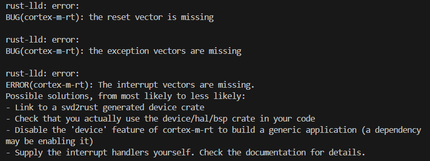
That means that you most probably forgot to add the entry point to your program. Make sure you add #[entry] before your main function so that the MCU knows to call it at startup.
Flash succeeds, the application does not start
In case your code doesn't seem to get uploaded correctly or the board goes into BOOTSEL mode as soon as you plug it into your computer, it might be time to debug. To install required dependencies for debugging, run these commands:
rustup component add llvm-tools

cargo install cargo-binutils
Now, you can run this command:
rust-objdump --section-headers target/thumbv6m-none-eabi/debug/<crate_name>
This will let us see the layout of the binary file, or the memory of the program that we are about to flash to the board.
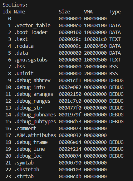
We need to make sure that it contains the .boot_loader section, or else our program will never run.
Further reading: Embassy Tutorial
Exercises
- Use KiCad to design a simple circuit that connects an LED to GPIO 0 (GP0). (1p)
The maximum current that GPIO pins output depends on the MCU. To be sure that the LED will work normally and there is no risk of destruction, a resistor has to be added to limit the current level below the maximum GPIO output current.
- Write a program using Embassy that set on HIGH the LED connected to GPIO pin 0 (GP0). (2p)
Please make sure the lab professor verifies your circuit before it is powered up.
- Write a program using Embassy that blinks the LED connected to GPIO pin 0 (GP0) every 300ms. (2p)
For the purpose of this lab, please use await as is, think that for using the Timer, you have to add .await after the after function.
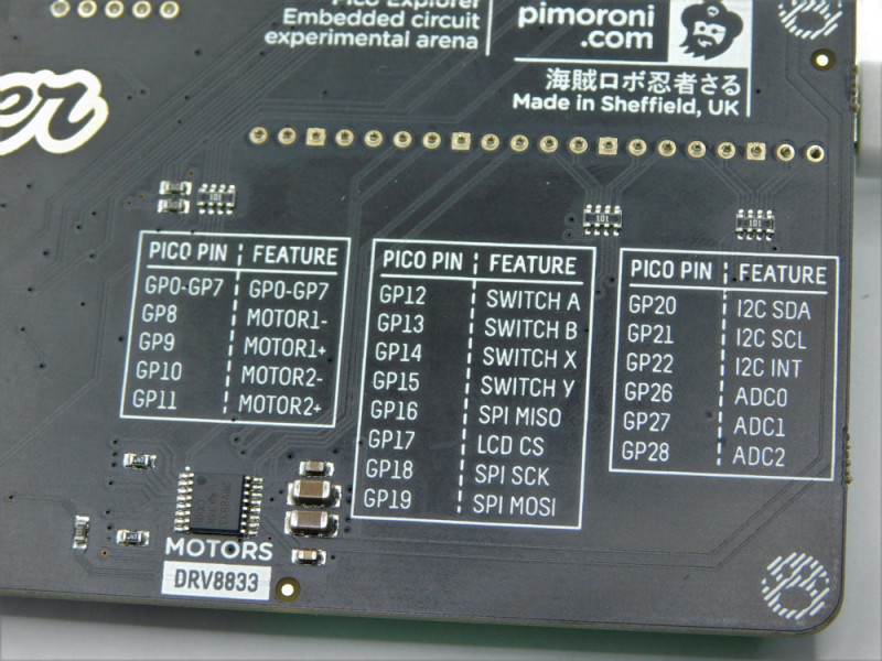
- Write a program using
embassy-rsthat will write the message "The button was pressed" to the console every time button A is pressed. Take a look at the Pico Explorer Base's pinout to determine the pin to which button A is connected. (2p)
The Raspberry Pi Pico does not have an integrated debugger, so writing messages to the console is done with a simulated serial port over the USB. This implies the usage of a USB driver.
use embassy_rp::usb::{Driver, InterruptHandler};
use embassy_rp::{bind_interrupts, peripherals::USB};
use log::info;

// Use for the serial over USB driver
bind_interrupts!(struct Irqs {
    USBCTRL_IRQ => InterruptHandler<USB>;
});


// The task used by the serial port driver
// over USB
#[embassy_executor::task]
async fn logger_task(driver: Driver<'static, USB>) {
    embassy_usb_logger::run!(1024, log::LevelFilter::Info, driver);
}

#[embassy_executor::main]
async fn main(spawner: Spawner) {
    let peripherals = embassy_rp::init(Default::default());

    // Start the serial port over USB driver
    let driver = Driver::new(peripherals.USB, Irqs);
    spawner.spawn(logger_task(driver)).unwrap();

    // ...

    info!("message");
}
Make sure you sleep while looping to read the button's value, otherwise the USB driver's task will not be able to run and the messages will not be printed.
:::
-
Write a Rust program using
embassy-rsthat toggles the LED every time button A is pressed. (1p) -
Write a Rust program that sets on HIGH the LED connected to GPIO pin 0 (GP0). (1p)
- use the
rp2040-paccrate - use bare metal
- use the
-
Write a Rust program that blinks the LED connected to GPIO pin 0 (GP0) every 300ms. (1p)
Advanced topics
Debouncing techniques for stable input reading.
Noise is produced whenever a pushbutton or other switch is moved. Because the switch contact is made of metal and has some elasticity, there is some noise (contact). The switch literally bounces a few times once it makes contact with a metal surface when it is shifted into a new position. This contact is known as bounce.

The image above shows the signal produced by a button when pressed.
The most correct way to correct the bouncing problem is the hardware one, but there are also software methods to correct the problem. For more details and examples, consult the documentation from Embassy-rs and the examples provided by them.