04 - PWM & ADC
This lab will teach you the difference between digital and analog signals, how to simulate analog signals by using Pulse Width Modulation (PWM) and how to convert analog signals to digital ones using Analog-to-Digital Converters (ADC).
Resources
-
Raspberry Pi Ltd, RP2040 Datasheet
- Chapter 2 - System Description
- Chapter 2.15 - Clocks
- Subchapter 2.15.1
- Subchapter 2.15.2
- Chapter 4 - Peripherals
- Chapter 4.5 - PWM
- Chapter 4.6 - Timer
- Chapter 4.9 - ADC and Temperature Sensor
- Subchapter 4.9.1
- Subchapter 4.9.2
- Subchapter 4.9.5
-
Paul Denisowski, Understanding PWM
Timing
In embedded applications, keeping track of time is crucial. Even for the simple task of blinking a led at a certain time interval, we need a reference of time that is constant and precise.
Clocks
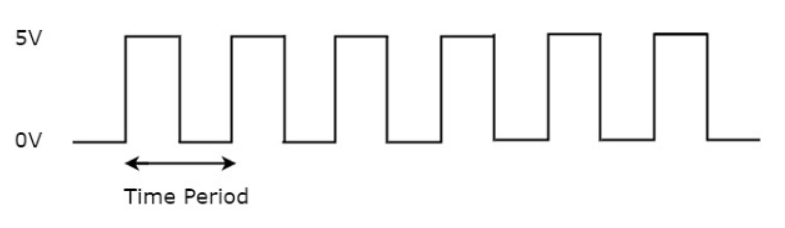
A clock is a piece of hardware that provides us with that reference. Its purpose is to oscillate at a fixed frequency and provide a signal that switches from high to low at a fixed interval.
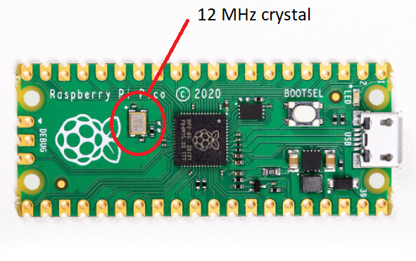
The most precise type of clock is the crystal oscillator (XOSC). The reason why it is so accurate is because it uses the crystal's natural vibration frequency to create the clock signal. This clock is usually external to the processor itself, but the processor also has an internal clock (ROSC) that is less accurate and that can be used in cases where small variations of clock pulses are negligeable. When using the USB protocol, for instance, a more stable clock signal is required, therefore the XOSC is necessary. The crystal oscillator on the Raspberry Pi Pico board has a frequency of 12MHz.
This clock signal is just a reference, and most of the time we need to adjust it to our needs. This is done by either multiplying or dividing the clock, or in other words, elevating or lowering the frequency of the clock. For example, the RP2040 itself runs on a 125MHz clock, so the crystal oscillator frequency of 12MHz is multiplied (this is done using a method called Phase-Locked Loop).
Counters
A counter is a piece of hardware logic that counts, as its name suggests. Every clock cycle, it increments the value of a register, until it overflows and starts anew.
A regular counter on 8 bits would count up from 0 to 255, then loop back to 0 and continue counting.
In theory a counter is associated with 3 registers:
| Register | Description |
|---|---|
value | the current value of the counter |
direction | whether the counter is counting UP or DOWN |
reset | if the direction is UP, the value at which the counter resets to 0; if the direction is DOWN, the value at which the counter reset after reaching 0 |

The way the counter works here is that it increments/decrements every clock cycle and checks whether or not it has reached its reset value. If is has, then it resets to its initial value and starts all over again.
SysTick
The ARM Cortex-M uses the SysTick time counter to keep track of time. This counter is decremented every microsecond, and when it reaches 0, it triggers an exception and then resets.
SYST_CVRregister - the value of the timer itselfSYST_RVRregister - the reset valueSYST_CSR_SETregister:ENABLEfield - enable/disable the counterTICKINTfield - enable/disable exception on reaching 0
Timers
Until now, we have been able to blink a led at a certain time interval, by busy waiting a while between each led toggle. The technique we used so far was asking the processor to skip a clock cycle a number of times, or by calling the processor instruction nop (no operation) in a loop.
This method is not ideal, since the nop instruction stalls the processor and wastes valuable time that could otherwise be used to do other things in the meantime. To optimize this, we can use alarms.
An alarm is a counter that triggers an interrupt every time it reaches a certain value. This way, an alarm can be set to trigger after a specific interval of time, and while it's waiting, the main program can continue executing instructions, and so it is not blocked. When the alarm reaches the chosen value, it goes off and triggers an interrupt that can then be handled in its specific ISR.

The RP2040 timer is fully monotomic, meaning it can never truly overflow. Its value is stored on 64 bits and increments every 1 microsecond, which means that the last value it can increment to before overflowing is 264-1, which the equivalent of roughly 500,000 years. This timer allows 4 different alarms, which can be used independently (TIMER_IRQ_0/1/2/3).
Analog and Digital Signals
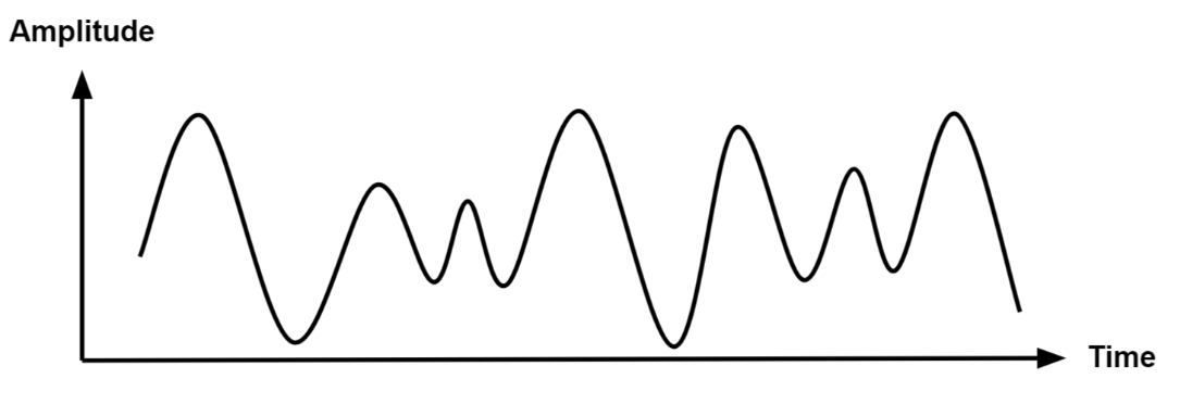
Analog signals are a representation of real-world data. They communicate information in a continuous function of time. They are smooth and time-varying waves, and contain an infinite number of values within the continuous range. An example of an analog signal would be sound, or the human voice.
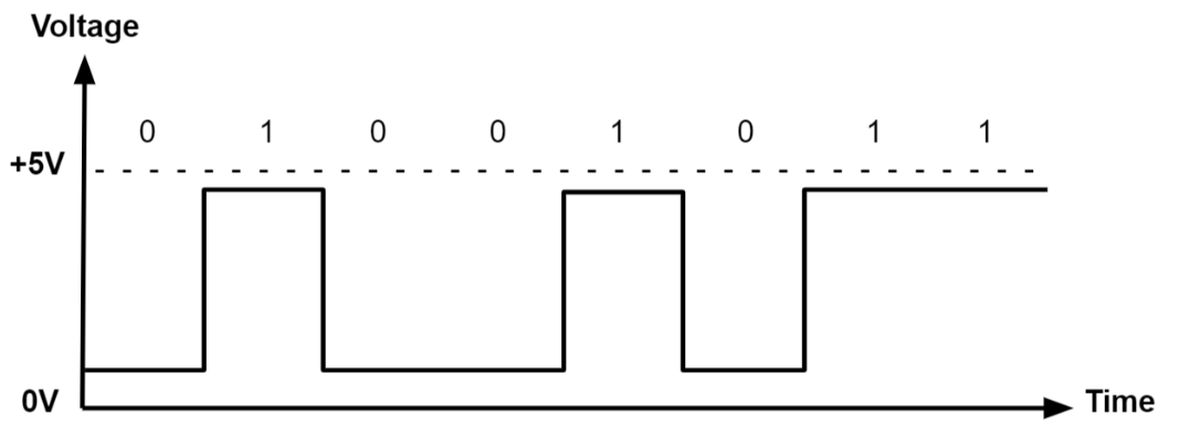
Digital signals are a discrete representation of data. They are represented by a sequence of binary values, taken from a finite set of possible numbers. They are square and discrete waves. In most cases, they are represented by two values: 0 and 1 (or 0V and 5V). Digital representation of signals is usually used in hardware.
Pulse-Width Modulation (PWM)
Up to now, we learned to turn a led on and off, or in other words, set a led's intensity to 100% or 0%. What if we wanted to turn on the led only at 50% intensity? We only have a two-level digital value, 0 or 1, so technically a value of 0.5 is not possible. What we can do is simulate this analog signal, so that it looks like the led is at half intensity.
Pulse-Width Modulation is a method of simulating an analog signal using a digital one, by varying the width of the generated square wave.
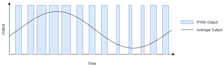
We can think of the simulated analog signal being directly proportional to the change in digital signal pulse size. The larger the square wave at a given period T, the higher the average analog amplitude output for that period.
The duty cycle of the signal is the percentage of time per period that the signal is high.
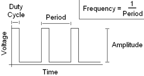
So if we wanted our led to be at 50% intensity, we would choose a duty cycle of 50%. By quickly switching between high and low, the led appears to the human eye as being at only 50% intensity, when in reality, it's only on at max intensity 50% of the time, and off the rest of the time.
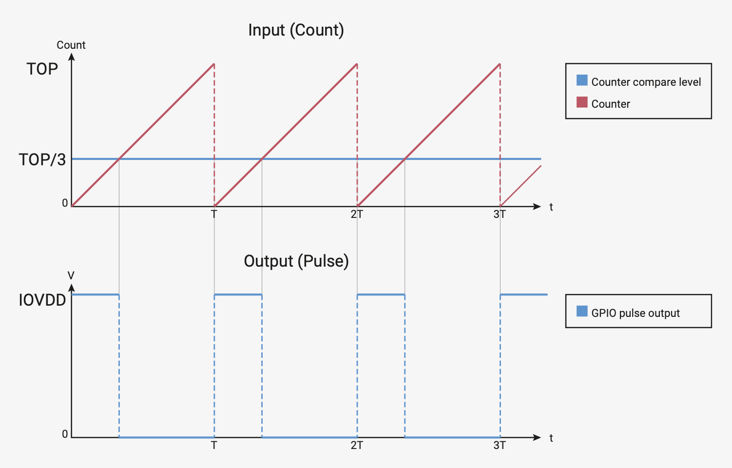
For the RP2040, to generate this PWM signal, a counter is used. The PWM counter is controlled by these registers (X can be from 0-7, depending on the channel):
CHX_CTR- the actual value of the counterCHX_CC- the value that the counter will compare toCHX_TOP- the value at which the counter will reset (or wrap)
When CHX_CTR is reset, the value of the output signal is 1. The counter counts up until it reaches CHX_CC, after which the value of the output signal becomes 0. The counter continues to count until it reaches CHX_TOP, and then the signal becomes 1 again. This way, by choosing the value of CHX_CC, we set the duty cycle of the PWM signal.
On RP2040, all GPIO pins support PWM. Every two pins share a PWM slice, and each one of them is on a separate channel.
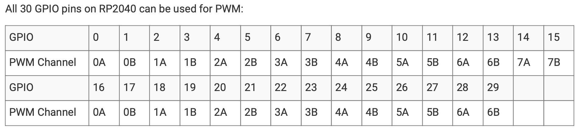
This means that in order to use a pin as PWM, we need to know what channel it's on, and which output it uses (A or B).
Examples of hardware controlled through PWM
- leds
- motors
- buzzers
- RGB leds (what we will be using for this lab)
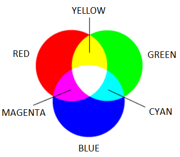
An RGB LED is a led that can emit any color, using a combination of red, green and blue light. On the inside, it's actually made up of 3 separate leds:
- R led - to control the intensity of the red light
- G led - to control the intensity of the green light
- B led - to control the intensity of the blue light
By using PWM on the R, G and B leds, we can control each of their intensity to represent any color.
For example, if we wanted to create the color purple, we would set the intensity of red and blue to 100%, and the intensity of green to 0%.
There are two different types of RGB LEDs:
- common cathode: all LED cathodes are connected together. A LOW signal means off, and a HIGH signal means on at max intensity.
- common anode: all LED anodes are connected together. A LOW signal means on at max intensity, and a HIGH signal means off.
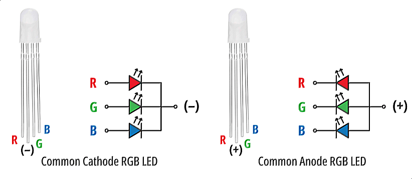
For this lab, we will be using common anode RGB LEDs, which means that the PWM signal should be opposite. 0 will be 100% intensity, and 1 will be 0% intensity.
How to wire an RGB LED
For common cathode RGB LEDs, we must tie each of the 3 color led legs to GPIO pins in series with a resistance, and connect the fourth pin to GND.
For common anode RGB LEDs, we must also tie each of the 3 color led legs to GPIO pins in series with a resistance, but connect the fourth pin to 3V3 instead.
Do not forget to tie a resistance to each color pin of the RGB LED!
PWM in Embassy-rs
First, we need a reference to all peripherals, as usual.
// Initialize peripherals
let peripherals = embassy_rp::init(Default::default());
In order to modify the PWM counter configurations, we need to create a Config for our PWM.
use embassy_rp::pwm::Config as ConfigPwm; // PWM config

// Create config for PWM slice
let mut config: ConfigPwm = Default::default();
// Set top value (value at which PWM counter will reset)
config.top = 0x8000; // in HEX, equals 32768 in decimal
// Set compare value (counter value at which the PWM signal will change from 1 to 0)
config.compare_a = config.top / 2;
In the example above:
topis the field fromConfigthat will define the value at which the counter will reset back to 0compare_ais the field fromConfigthat will define the value at which the PWM signal will switch from 1 to 0 In this case,config.compare_ais half ofconfig.top. This means that the duty cycle of the generated PWM signal will be 50%, or, in other words, that the PWM signal will switch from 1 to 0 halfway through each period.
To select the pin that we want to use for PWM, we need to create a new PWM driver that uses the correct channel and output for our pin.
// Create PWM driver for pin 0
let mut pwm = Pwm::new_output_a( // output A
    peripherals.PWM_CH0, // channel 0
    peripherals.PIN_0, // pin 0
    config.clone()
);
- The code above is an example for pin 0. You need to modify the channel, output and pin depending on the PWM pin you choose to use!
- The value of
compare_aorcompare_bmust be changed depending on the desired duty cycle!
If we decide to modify the value of compare_a or compare_b, we have to update the configuration for the PWM.
config.compare_a += 100; // modified value of `compare_a`
pwm.set_config(&config); // set the new configuration for PWM
Analog-to-Digital Converter (ADC)
Now we know how to represent an analog signal using digital signals. There are plenty of cases in which we need to know how to transform an analog signal into a digital one, for example a temperature reading, or the voice of a person. This means that we need to correctly represent a continuous wave of infinite values to a discrete wave of a finite set of values. For this, we need to sample the analog signal periodically, in other words to measure the analog signal at a fixed interval of time. This is done by using an Analog-to-Digital converter.
The ADC has two important parameters that define the quality of the signal representation:
| Parameter | Description | Impact on quality |
|---|---|---|
| Sampling Rate | Frequency at which a new sample is read | The higher the sampling rate, the more samples we get, so the more accurate the representation of the signal |
| Resolution | Number of bits which we can use in order to store the value of the sample | The higher the resolution, the more values we can store, so the more accurate the representation |
For example, a resolution of 8 bits means that we can approximate the analog signal to a value from 0 to 255.

Nyquist-Shannon Sampling Theorem
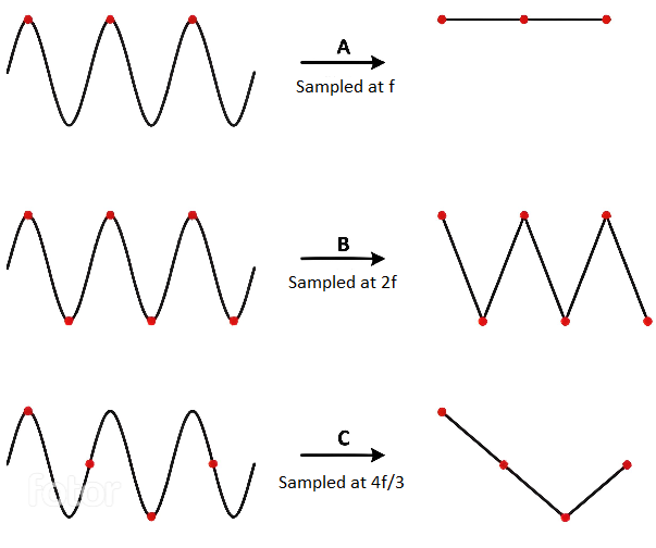
The Nyquist-Shannon sampling theorem serves as a bridge between continuous-time signals and discrete-time signals. It establishes a link between the frequency range of a signal and the sample rate required to avoid a type of distortion called aliasing. Aliasing occurs when a signal is not sampled fast enough to construct an accurate waveform representation.
For an analog signal to be represented without loss of information, the conversion needs to satisfy the following formula:
The analog signal needs to be sampled at a frequency greater than twice the maximum frequency of the signal. In other words, we must sample at least twice per cycle.
Examples of analog sensors
- temperature sensor
- potentiometer
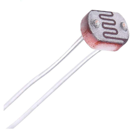
- photoresistor (what we will be using for this lab)
A photoresistor (or photocell) is a sensor that measures the intensity of light around it. Its internal resistance varies depending on the light hitting its surface; therefore, the more light there is, the lower the resistance will be.
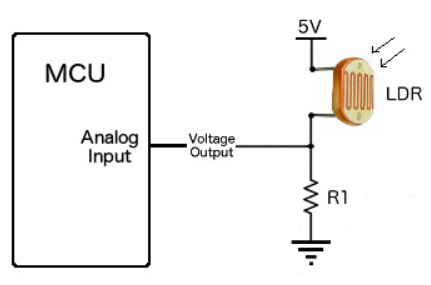
How to wire a photoresistor
To wire a photoresistor, we need to connect one leg to GND and the other leg to a voltage divider. We remember from Lab 01 - Hardware Introduction that:
In our case:
- will be the voltage at the ADC pin on the MCU
- will be the voltage at the from the GPIO pin the photoresistor is tied to
- is the variable resistance of the photoresistor
- is a resistance compatible with our photoresistor (in our case, 10k )
This way, the ADC pin measures the photoresistor's resistance, without the risk of a short-circuit.
ADC in Embassy-rs
On the RP2040, ADC uses an interrupt called ADC_IRQ_FIFO to signal whenever a new sample has been added to the ADCs' FIFO. This new sample will be stored inside a FIFO. In the Embassy library, this interrupt is already implemented, so all we need to do is bind it and use it in our ADC variable.
// Bind the `ADC_IRQ_FIFO` interrupt to the Embassy's ADC handler
bind_interrupts!(struct Irqs {
    ADC_IRQ_FIFO => InterruptHandler;
});

// ---- fn main() ----

// Initialize peripherals
let peripherals = embassy_rp::init(Default::default());

// Create ADC driver
let mut adc = Adc::new(peripherals.ADC, Irqs, Config::default());
If we are using PWM and ADC in the same code, we will have two different Config imports with the same name. In order to avoid compilation errors, we need to separate the PWM config import from the ADC one. To do this, we can import the two Configs with different names.
use embassy_rp::adc::Config as ConfigAdc; // ADC config

// ---- fn main() ----
let mut adc = Adc::new(peripherals.ADC, Irqs, ConfigAdc::default());
Now, we need to initialize the ADC pin we will be using. The Raspberry Pi Pico has 3 pins that support ADC: ADC0, ADC1, and ADC2.
// Initialize ADC pin
let mut adc_pin = Channel::new_pin(peripherals.PIN_X, Pull::None); // where X should be replaced with a pin number
Once we have the ADC and pin set up, we can start reading values from the pin.
let level = adc.read(&mut adc_pin).await.unwrap(); // read a value from the pin
info!("Light sensor reading: {}", level); // print the value over serial
Timer::after_secs(1).await; // wait a bit before reading and printing another value
Exercises
- Connect an LED to pin GP2, a photo-resistor to ADC0 and an RGB LED to pins GP1, GP3, GP4. Use KiCad to draw the schematics. (1p)
- Take a look at
lab04_ex2in the lab skeleton. It is a working example of lighting an LED using PWM at 50% intensity. The LED in the example is connected to GP0.- Modify the provided example to light the LED of your circuit to 25% intensity. (1p)
- Increase the LED's intensity by 10% every second, until it reaches max intensity, when it stops. (1p)
- Read the value of the photo-resistor and print it to the console. (2p)
To see the console with messages from the Pico, use the flash command with an extra -s parameter.
elf2uf2-rs -s -d /target/thumbv6m-none-eabi/debug/<crate_name>
To be able to print messages to the console, we need to send messages over a simulated serial port to the computer. For this, we will use the USB driver provided by Embassy.
use embassy_rp::usb::{Driver, InterruptHandler};
use embassy_rp::{bind_interrupts, peripherals::USB};
use log::info;

// Use for the serial over USB driver
bind_interrupts!(struct Irqs {
    USBCTRL_IRQ => InterruptHandler<USB>;
});


// The task used by the serial port driver
// over USB
#[embassy_executor::task]
async fn logger_task(driver: Driver<'static, USB>) {
    embassy_usb_logger::run!(1024, log::LevelFilter::Info, driver);
}

#[embassy_executor::main]
async fn main(spawner: Spawner) {
    let peripherals = embassy_rp::init(Default::default());

    // Start the serial port over USB driver
    let driver = Driver::new(peripherals.USB, Irqs);
    spawner.spawn(logger_task(driver)).unwrap();

    // ...

    info!("message");
}
Notice that the USB driver also uses an InterruptHandler import that could be confused with the InterruptHandler used by ADC. Make sure to use different naming conventions for each one, as described in the warning here.
- Depending on the value read from the photo-resistor, brighten or dim the led. The led should shine brighter when there is less light in the room. (2p)
Use the serial console to debug your program!
- Make the RGB LED switch from red -> yellow -> blue every time the switch A is pressed. (2p)
The reason why we can't use GP1, GP2 and GP3 for the RGB LED, for example, is because GP2 and GP3 are both on PWM channel 1, therefore we can't independently control them with PWM.
- Using the
SysTickinterrupt in bare metal, make the led blink at a 100ms delay. (1p)
Setting up the SysTick counter:
const SYST_RVR: *mut u32 = 0xe000_e014 as *mut u32;
const SYST_CVR: *mut u32 = 0xe000_e018 as *mut u32;
const SYST_CSR: *mut u32 = 0xe000_e010 as *mut u32;

// fire systick every 5 seconds
let interval: u32 = 5_000_000;
unsafe {
    write_volatile(SYST_RVR, interval);
    write_volatile(SYST_CVR, 0);

    // set fields `ENABLE` and `TICKINT`
    write_volatile(SYST_CSR, 0b011);
    // we need to write the whole register, single bit modifications is not possible with the SYST_CSR register
}
Registering the SysTick handler:
#[exception]
unsafe fn SysTick() {
    /* systick fired */
}
To blink the led in bare metal, use the code provided in Lab 03 - Exceptions & Interrupts.
To safely share a bool value globally to keep track of the LED status, we need to use an AtomicBool. This requires less code than using a normal bool and a Mutex.
Creating a new static AtomicBool:
// imports
use core::sync::atomic::{AtomicBool, Ordering};

static atomic_bool: AtomicBool = AtomicBool::new(false);
Reading the value of an AtomicBool:
let atomic_bool_value = atomic_bool.load(Ordering::Relaxed);
Writing the value of an AtomicBool:
atomic_bool.store(true, Ordering::Relaxed);