08 - Wi-Fi
This lab will teach you the basics of networking and Wi-Fi, and how to use Wi-Fi with the Raspberry Pi Pico W, in Embassy.
Resources
Andrew Tanenbaum, Computer networks (5th edition)
- Chapter 1 - Introduction
- Subchapter 1.4.2 - The TCP/IP Reference Model
Networking basics
A network is a set of devices that are linked together in order to share resources. Most of the time, devices communicate to one another within a network using a set of protocols based on a network communication standard called the OSI (Open Systems Intercommunication) Stack.
The OSI stack has 7 layers, out of which 5 are important:
- L1 - hardware layer - transmission of bits through a physical medium (copper wire, radio waves, optical fibre)
- L2 - data link layer - transmission of packets between two devices in a network (Ethernet, Wi-Fi)
- L3 - network layer - transmission of packets between devices in different networks (IP)
- L4 - transport - transmission of data from a source to a destination (TCP, UDP)
- L7 - application - transmission of data from an application (port) of a device to an application of another device
More information on the OSI model can be found in Lecture 08 - Networking.
Devices that communicate in a network have associated addresses. In a TCP/IP network these addresses are called IP (Internet Protocol) addresses. There are two types of IP addresses:
- IPv4 - stored on 32 bits
- IPv6 - newer, stored on 128 bits
The IPv6 solves the problem of an evergrowing number of devices with networking capabilities; a higher resolution for the IP address means more unique addresses that can be assigned. We will be discussing only the IPv4 in this lab, since it is most commonly used in local networks.
IPv4
An IPv4 address looks like this:
192.168.0.1/24
Each number separated by a dot is represented on 8 bits (ranging from 0 to 255). The number after the slash is the network mask, which will be described shortly.
The IP address can also be represented in hexadecimal or binary form. Usually, when configuring subnets, it's easier to use the binary form to perform the necessary calculations.
192.168.0.1 = 11000000.10101000.00000000.00000001
An IP address is made of two parts:
- network prefix: defines the network the device is a part of
- host identifier: is unique to the device in the network
The network mask defines the number of bits that are used to represent the network prefix. The smaller the mask, the more unique devices can exist in the network.
For example, for the above address 192.168.0.1/24, we know that the network prefix is 24 bits long. Therefore, the first 24 bits give us the network prefix and the last 8 bits give us the host identifier. The mask in this case would look like this: 255.255.255.0.
In binary, 255.255.255.0 is 11111111.11111111.11111111.00000000.
The first 24 bits are 1, the last 8 bits are 0.
Any device that wants to communicate in this local network (or subnet) must have an address ranging from 192.168.0.1 to 192.168.0.254. Note that the first 24 bits of the address are the same: the network prefix for these addresses is the same, since they can all be allocated to devices within the same network.


In the above example, 192.168.0.0 is the network address, and 192.168.0.255 is the broadcast address (used to broadcast to all endpoints in a subnet). The first and last possible addresses in a subnet are reserved and should not be assigned to devices.
To determine the network address, we need to perform a logic AND operation between the IP address and the network mask.
To determine the broadcast address, we need to perform a logic OR operation between the IP address and the inverse of the network mask.
This means converting the IP address and network mask to binary, then performing AND or OR on every bit, then converting it back to decimal.
Learn more about subnetting here.
Routers
Routers are devices that forward packets between networks. The packets of the sender will be routed to the receiver of a different network, depending on the IP of the destination, passing from one router to another until they reach their destination. This happens through complex routing protocols. Routers also deal with traffic filtering, DNS (Domain Name System), DHCP and others.
The default gateway in a local network is the router where packets must be sent when the destination IP is not in the current local network. From there, packets will be routed further. Read more about it here.
A L3 (Network) packet looks like this:

The L3 packet is contained within the L2 frame. The L2 packet headers contain the MAC address of the source and the destination, and the data contains the L3 packet. The L3 packet has a separate header, with the IP address of the source and the destination. The router is an L3 network device, meaning it is able to descifer the IP address of the source and the destination from the L3 frame and determine where the packet needs to be routed to.

DHCP
Dynamic Host Configuration Protocol (DHCP) is a network management protocol used by routers to dynamically allocate IP addresses to devices connected to its network. Routers dynamically assign addresses to new devices in the network, if they don't already have a static IP. DHCP leases IP, Mask, Gateway and DNS servers.
Networking protocols
TCP (Transmission Control Protocol)
TCP is connection-oriented, meaning that a connection must be first established between two devices (client and server) before data can be sent. Packets that are not received correctly must be retransmitted by the sender, ensuring that data always reaches its destination. The packet might also be fragmented during the transmission and the receiver might receive it in several smaller packets. TCP is used in cases where data integrity is most important.
UDP (User Datagram Protocol)
UDP, on the other hand, is connectionless, and prioritizes time over reliability. Packets that are not received correctly are dropped,not retransmitted and not fragmented. UDP is used in time-sensitive applications, such as audio streaming.
Wi-Fi
Wi-Fi is a networking technology that allows devices to wirelessly communicate in a local network or interface the Internet.
Wi-Fi devices use radio waves to transmit data to one another in a network, through wireless access points (a wireless router, for instance). The access point (AP) connects directly to a local area network (LAN) and provides wireless connections for other devices in its proximity to use.
Protocol
Wi-Fi uses the 802.11 IEEE standard, with different radio technologies:
- 2.4 GHz radio band, ultra high frequency, (widely supported; Raspberry Pi Pico W uses this frequency)
- 5 GHz radio band, super high frequency
- others, not widely used
Each radio frequency range is divided into a multitude of channels. Each device that uses a frequency band communicates over one channel. Ideally, each device is allocated a separate channel. Sometimes, though, when there are many devices using a Wi-Fi frequency band, devices might end up having to share a channel and wait their turn to transmit data, leading to lower communication speeds. 5 GHz provides more channels than 2.4 GHz, allowing more devices to use the band without interference.
Security
Open Wi-Fi
Open wireless networks don't require any authentication, and all transmissions are unencrypted. Any device that connects to an open network can easily intercept data sent in this network. This is unsecured and unsafe.
Wired Equivalent Privacy (WEP)
WEP is the first security protocol ever implemented. It uses data encryption based on generated key values. It was designed in 1997 and has since become obsolete, because it is really easy to crack and basically as unsafe as open Wi-Fi.
Wi-Fi Protected Access (WPA/WPA2/WPA3)
WPA, WPA2 and WPA3 were defined in response to the serious weaknesses discovered in WEP. Each version of WPA increments the security of the protocol, using more powerful password encryption methods.
Wi-Fi on the Raspberry Pi Pico
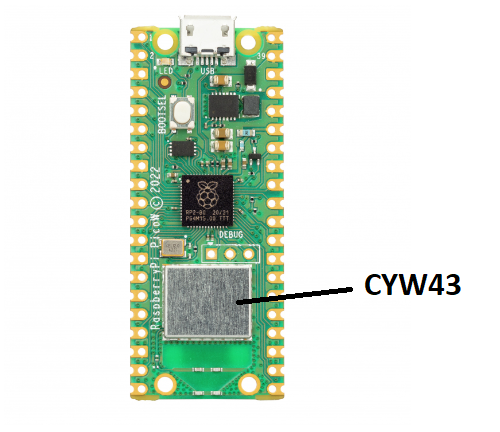
Apart from the RP2040 microcontroller, the Raspberry Pi Pico board also has a separate, on-board wireless interface. It is a 2.4 GHz Infineon chip, CYW43439. This chip deals only with Wi-Fi (and Bluetooth) communication, and it is connected to the RP2040 via SPI.
Wi-Fi in Embassy
Initialise the peripherals first, as usual.
let peripherals = embassy_rp::init(Default::default());
The CYW43 chip also needs to be programmed in order to handle the Wi-Fi connection and transfers. For this, Infineon provides two firmware binaries that need to be built together with our program. We use the include_bytes! macro to achieve this.
let fw = include_bytes!("../cyw43-firmware/43439A0.bin");
let clm = include_bytes!("../cyw43-firmware/43439A0_clm.bin");
The above example assumes that the binaries have been downloaded and added to the <crate_root>/cyw43-firmware folder. They can be downloaded from here.
The include_bytes! macro is built-in by the compiler. It links the cyw43 binaries to our program binary during compilation.
Next, we need to declare the SPI that interfaces the Wi-Fi chip. This SPI will be controlled by PIO (Programmable Input/Output), instead of simple GPIO pins, as we've done so far. PIO contains dedicated hardware that can deal with high-speed input and output operations, therefore offloading the MCU.
let pwr = Output::new(p.PIN_23, Level::Low);
let cs = Output::new(p.PIN_25, Level::High);
let mut pio = Pio::new(p.PIO0, Irqs);
let spi = PioSpi::new(&mut pio.common, pio.sm0, pio.irq0, cs, p.PIN_24, p.PIN_29, p.DMA_CH0);
We're also going to need to bind the interrupts that can be triggered by the PIO.
bind_interrupts!(struct Irqs {
    PIO0_IRQ_0 => InterruptHandler<PIO0>;
});
CYW43 driver
Now we need to instantiate the CYW43 driver, and spawn a task that will start it.
static STATE: StaticCell<cyw43::State> = StaticCell::new();
let state = STATE.init(cyw43::State::new());
let (net_device, mut control, runner) = cyw43::new(state, pwr, spi, fw).await;
spawner.spawn(wifi_task(runner)).unwrap();

control.init(clm).await;
control
    .set_power_management(cyw43::PowerManagementMode::PowerSave)
    .await;
Inside this task, the driver will deal with the low-level SPI transfers between the MCU and the Wi-Fi chip.
#[embassy_executor::task]
async fn wifi_task(runner: cyw43::Runner<'static, Output<'static>, PioSpi<'static, PIO0, 0, DMA_CH0>>) -> ! {
    runner.run().await
}
Network stack
To be able to communicate in a network, our device needs to have an associated IP address. We can configure a static IP address, or we can use DHCP to have an IP address dynamically assigned to our device.
- Static IP address In this case, the device defines its own IP address for the WLAN. For this, we also need to know the address of the default gateway.
let config = embassy_net::Config::ipv4_static(embassy_net::StaticConfigV4 {
   address: Ipv4Cidr::new(Ipv4Address::new(192, 168, 69, 2), 24),
   dns_servers: Vec::new(),
   gateway: Some(Ipv4Address::new(192, 168, 69, 1)),
});
- Dynamic IP address In this case, our device asks for an IP address via DHCP. It also receives other configuration information, such as the default gateway.
This method takes more time, because the device needs to wait to receive an IP address before it can start communicating in the network.
let config = Config::dhcpv4(Default::default());
Once we have defined the configuration, we need to instantiate and run the network stack driver, to be able to connect to the WLAN.
// Generate random seed
let seed = 0x0123_4567_89ab_cdef; // chosen by fair dice roll. guarenteed to be random.

// Init network stack
static STACK: StaticCell<Stack<cyw43::NetDriver<'static>>> = StaticCell::new();
static RESOURCES: StaticCell<StackResources<2>> = StaticCell::new();
let stack = &*STACK.init(Stack::new(
    net_device,
    config,
    RESOURCES.init(StackResources::<2>::new()),
    seed,
));

spawner.spawn(net_task(stack));
The network driver deals with the network stack: receiving, building and sending packets over the WLAN.
#[embassy_executor::task]
async fn net_task(stack: &'static Stack<cyw43::NetDriver<'static>>) -> ! {
    stack.run().await
}
Scanning for Wi-Fi networks
The CYW43 driver has a function that allows us to scan all Wi-Fi access points in the device's proximity.
let mut scanner = control.scan(Default::default()).await;
while let Some(bss) = scanner.next().await {
    if let Ok(ssid_str) = core::str::from_utf8(&bss.ssid) {
        info!("Scanned {}", ssid_str);
    }
}
The ssid is the name of the AP.
Connecting to a Wi-Fi Access Point
To connect to a WPA2 Wi-Fi network, we can use the join_wpa2 function, providing the network name and the password.
loop {
    match control.join_wpa2(WIFI_NETWORK, WIFI_PASSWORD).await {
        Ok(_) => break,
        Err(err) => {
            info!("join failed with status={}", err.status);
        }
    }
}

// Wait for DHCP, not necessary when using static IP
info!("waiting for DHCP...");
while !stack.is_config_up() {
    Timer::after_millis(100).await;
}
info!("DHCP is now up!");
To connect to an open network, we must use the join_open function instead.
control.join_open(WIFI_NETWORK).await;
Creating a Wi-Fi Access Point
The Pico can also be used as an Access Point, that other devices can connect to. We can initialize it as either an open network:
control.start_ap_open("Pico AP", 5).await;
or as a secured, WPA2 network:
control.start_ap_wpa2("Pico AP", "WeloveRust", 5).await;
Starting a TCP server
Now that we have connected our Pico to a Wi-Fi network, we can start a server to handle connections to our Pico.
We can to create a TCP socket in order to handle TCP connections and transfers.
let mut socket = TcpSocket::new(stack, &mut rx_buffer, &mut tx_buffer);
socket.set_timeout(Some(Duration::from_secs(10)));
Next, we wait for a connection on a specific port. For example, the following snippet waits for a TCP connection on port 1234.
control.gpio_set(0, false).await;
info!("Listening on TCP:1234...");
if let Err(e) = socket.accept(1234).await {
    warn!("accept error: {:?}", e);
    continue;
}

info!("Received connection from {:?}", socket.remote_endpoint());
control.gpio_set(0, true).await;
Once we have an established connection, we can read and write to the socket, and communicate with the other endpoint.
loop {
    let n = match socket.read(&mut buf).await {
        Ok(0) => {
            warn!("read EOF");
            break;
        }
        Ok(n) => n,
        Err(e) => {
            warn!("read error: {:?}", e);
            break;
        }
    };

    info!("rxd {}", from_utf8(&buf[..n]).unwrap());

    match socket.write_all(&buf[..n]).await {
        Ok(()) => {}
        Err(e) => {
            warn!("write error: {:?}", e);
            break;
        }
    };
}
Starting an UDP server
Similarly to the TCP server, we create a new socket, this time one that handles UDP connections.
let mut rx_buffer = [0; 4096];
let mut rx_metadata_buffer = [PacketMetadata::EMPTY; 3];
let mut tx_buffer = [0; 4096];
let mut tx_metadata_buffer = [PacketMetadata::EMPTY; 3];

let mut buf = [0u8; 4096];

let mut socket = UdpSocket::new(
    stack, &mut rx_metadata_buffer, &mut rx_buffer, &mut tx_metadata_buffer, &mut tx_buffer
);
Next, we bind our socket to a port (for example port 1234). Note that the bind function is not a future, since we don't need to wait for connections before initiating a transmission.
if let Err(e) = socket.bind(1234) {
    warn!("accept error: {:?}", e);
    continue;
}
Now, we can read and write to the socket, and any endpoint that connects to the port can send/receive data.
// example read
loop {
    match socket.recv_from(&mut buf).await {
        Ok((n, endpoint)) => {
            info!("Received from {:?}: {:?}", endpoint, from_utf8(&buf[..n]).unwrap());
        },
        Err(_) => {
            info!("An error occurred when receiving the packet!");
        }
    }
}

// example write
let buffer = "hello\n".as_bytes();
match socket.send_to(&buffer, IpEndpoint::new(IpAddress::v4(192, 168, 100, 45), 1234)).await {
    Ok(()) => {
        info!("sent")
    }
    Err(e) => {
        warn!("send error: {:?}", e);
    }
}
Since UDP is connectionless, to send data to an endpoint we need to specify exactly to which IP address and port we want to send it to.
Connecting as a client to a TCP server
The Pico can connect as a client to a TCP server using the connect function:
if let Err(e) = socket.connect(IpEndpoint::new(IpAddress::v4(1,2,3,5), 1234)).await {
    warn!("accept error: {:?}", e);
    continue;
}
Exercises
- The lab skeleton contains an example of setting up the Wi-Fi and connecting to an access point.
- Scan for local networks. (1p)
- Modify the code in order to connect to an existing network. Once connected, determine the IP address that has been assigned to the Pico through DHCP and the default gateway of the network. (1p)
You can use stack.config_v4() to find the assigned IP address and default gateway.
- Use a static IP address instead of a dynamic one. You can use the IP determined at the previous point. (1p)
- Test the example by connecting your computer to the Pico through Wi-Fi. Use the Wyliodrin network, the password will be written on the blackboard. Connect both the Pi and the laptop. Use
netcator any alternative to send a TCP packet to the Pico server from your computer. You should receive back the same string. (1p)
On Windows, you can use NCat. The command for establishing a TCP connection is:
ncat [ip_address] [port]
To send a packet, write any string in the terminal and press enter. You should receive back the same string, since this is what our server is currently configured to do.
You can run ncat -h to see a list of other available parameters for this command.
- Start a server on the pico that sends a message through Wi-Fi to your computer whenever a button is pressed. Use an UDP socket instead of TCP. (2p)
Use both netcat and the provided server code to open an UDP client socket on your PC that receives the messages from the Pico. Just create a new crate in a different folder with cargo init, then use the following code snippet:
use tokio::net::UdpSocket;
use std::{io, str::from_utf8};

#[tokio::main]
async fn main() -> io::Result<()> {
    let sock = UdpSocket::bind("0.0.0.0:1234").await?; // 0.0.0.0 means any network interface
    let mut buf = [0; 1024];
    loop {
        let (len, addr) = sock.recv_from(&mut buf).await?;
        println!("Received from {:?}", addr);
        println!("{}", from_utf8(&buf[..len]).unwrap().trim());
    }
}
Then, modify the Cargo.toml dependencies by adding this line: tokio = { version = "1", features = ["full"] }, or use cargo add tokio --features=full. Then run cargo run.
You will need to specify the IP address of your computer in the send_to function to send the message. The port is also required; we can use the -p argument for ncat to specify on which port the computer should listen for the message, or if you're using the Rust server, you can modify the port in the code (0.0.0.0:port).
You can transform a string slice to bytes using as_bytes().
- Modify the server so that you can also receive commands from your computer to turn an LED on and off. (1p)
led:on- command for turning on the LEDled:off- command for turning off the LED
Use select to await multiple futures (wait for button press and read from socket). Refer to Lab 5.
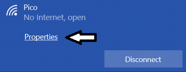
- Configure the Pico as an access point. You will need to set a static IP address both for the Pico and your computer, to make sure they are both in the same subnet, so that they can communicate. (1p)
To set a static IP for your computer when connecting to the Pico, choose "Properties" and configure the static IP for your computer there.
- Connect two Picos together through Wi-Fi. Control the LED connected to one Pico through a button connected to the second Pico. One team can configure the connection for the LED Pico (server side), and another team the connection for the button Pico (client side). (2p)
button:pressed- signal for the button press