02 - GPIO
The purpose of this lab is to understand how to start developing firmware in Rust with Embassy for the STM32U545 and RP2 MCUs.
Concepts
- How to setup an empty project that uses Embassy;
- How to use the lab board;
- How to use GPIO pins from Embassy;
- How to use the lab board's LEDs
- How to use the lab board's switches
Resources
- Embassy Book - an overview of the Embassy framework
- For Beginners
embassy-stm32's Documentation - the API for the STM32U545embassy-rp's Documentation - the API for the RP2040 and RP2350- The Rusty Bits, Intro to Embassy : embedded development with async Rust
Extra Resources
- STMicroelectronics, STM32U545 Datasheet
- Raspberry Pi Ltd, RP2350 Datasheet
- Raspberry Pi Ltd, Raspberry Pi Pico 2 Datasheet
- Raspberry Pi Ltd, Raspberry Pi Pico 2W Datasheet
What is GPIO?
General-Purpose Input/Output, or GPIO, is an essential part of embedded systems that serves as a vital conduit between microcontrollers and microprocessors and the outside world. A microcontroller or microprocessor's group of pins that can each be set to operate as an input or an output is referred to as GPIO. The purpose of these pins is to interface external components, including actuators, displays, sensors, and other devices, so that the embedded system may communicate with its surroundings. Standardised communication protocols like SPI, I2C, PCM, PWM, and serial communication may be directly supported by some GPIO pins. There are two varieties of GPIO pins: digital and analog.
Configuring GPIO Pins
GPIO pins can be used as outputs (LEDs, motors, buzzers) or as inputs (buttons, sensors).
Every pin of the MCU can perform multiple functions. Several peripherals need to use input and output pins. It is the role of the IO Bank0 to multiplex and connect the peripherals to the pins.
- STM32 Nucleo-U545RE-Q
- Raspberry Pi Pico 2
The STM32U545 controls the GPIO pins through several GPIO Ports (PortA, PortB, PortC, PortD, PortE, etc.). Using GPIOs implies configuring the:
- MODER - connects the outer GPIO pin to one of the:
- internal
GPIOperipheral asinput - internal
GPIOperipheral asoutput - one of the alternate function peripheral (further selected by the Alternate Function Multiplexer)
- the
ADCperipheral
- internal
- Electrical Configuration - manages the physical pin on the outside of the chip. It decides the electrical behavior of the pad, such as whether it has a pull‑up or pull‑down resistor, whether it drives strongly or weakly, and whether it is push‑pull or open‑drain.
- Alternate Function Multiplexer - connects the internal peripherals to the outside pins. Each pin can be switched to different functions. For example, a single pin can be used as:
- a
UARTtransmit line - an
I2Cdata line - an
SPIclock or data line - a
TIMtimer channel - a
PWMtimer channel - ...
- a
- GPIO Input/Output - this is the simple digital interface that developers use when they want to read or write a pin directly in software. It’s what you use to toggle an LED or read a button.


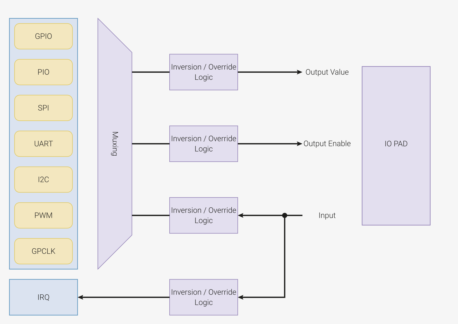
The RP2040 and RP2350 have three peripherals that control the GPIO pins:
- Pads - control the actual physical pin or pad that the processor has outside. They control the electrical parameters, like maximum current or pull up and pull down resistors
- IO Bank0 - connects and multiplexes the peripheral's pins to the output pads. Several peripherals use the same output pad to communicate with the exterior. For example, in the image below,
GPIO0can be used either for:SIO- theGPIOfunctionSPI_RX- the receive pin for theSPIperipheralI2C0_SDA- the data pin for theI2C0peripheralUART0_TX- the transmit pin for theUART0(serial port 0) peripheral
- SIO - that controls the interior MCU's pins. This is the peripheral that developers use to read and write the value of the pins.

Hardware access
There are 3 different ways in which the hardware either on the STM32 Nucleo-U545RE-Q or the Raspberry Pi Pico 2 can be used:
- Embassy framework, with the Embedded HAL implementation
- Platform Access Crate (PAC)
- Bare metal
Embassy Framework
Developing bare metal firmware requires a lot of time.
In trying to standardize firmware development, The Rust Embedded devices Working Group has designed a set of standard traits (interfaces) for interacting with an MCU. This is called the Embedded Hardware Abstraction Layer, or shortly Embedded HAL. The main purpose is to define a common hardware interface that frameworks, libraries and operating systems can build upon. Regardless of what MCUs the device is using, the upper level software should be as portable as possible.
There are several crates that implement the Embedded HAL traits for the STM32U545, RP2040 and RP2350 MCUs. These crates are called HAL Implementations.
- embassy-stm32 - crate implements the Embedded HAL for STM32U545 that is used with the embassy-rs framework
- rp2350_hal crate, implements just the embedded HAL traits, it is the bare minimum for developing RP2350 applications
- rp2040_hal crate, implements just the embedded HAL traits, it is the bare minimum for developing RP2040 applications
- embassy-rp crate implements the Embedded HAL for RP2040 and RP2350 that is used with the embassy-rs framework
Several frameworks are available on top of the HAL Implementations to speed things up. The most common used ones are:
- RTIC - The hardware accelerated Rust RTOS - A concurrency framework for building real-time systems
- Embassy - The next-generation framework for embedded applications
The Software Stack
Embassy is a full fledged embedded framework for Rust embedded development. Besides the implementation of the embedded HAL for different MCUs (STM32U545, RP2350 and RP2040 included), Embassy provides several functions like timers, BLE and network communication.

The crates used by Embassy and their mapping are shown in the table below.
| Crate | Position |
|---|---|
embassy-executor | Framework |
smoltcp, defmt | Libraries |
embassy-net, embassy-time, embassy-usb, embassy-usb-logger | Framework Driver |
embassy-usb-driver, embassy-time-driver | Embassy HAL (API) |
cyw43, cyw43-pio | Driver (WiFi) |
embedded-hal, embedded-hal-async | Rust Embedded HAL (Standard) |
embassy_stm32, embassy_rp | HAL Implementation |
cortex-m, cortex-m-rt | μ-architecture crates |
stm32-metapac, rp_pac | Platform Access Crate |
The name Embassy is derived from Embedded Asynchronous Rust.
Empty Embassy Firmware
The Embassy Framework is a collection of crates. Building an empty firmware that uses embassy requires:
- adding the Embassy HAL Implementation for a specific board, in this case STM32U545 or RP2350;
- adding the core Embassy crates, that provide the executor, timers and futures;
- adding the
cortex-m-rtanddefmtcrates that Embassy requires.
- STM32 Nucleo-U545RE-Q
- Raspberry Pi Pico 2
- Raspberry Pi Pico
[dependencies]
embassy-stm32 = { version = "0.4.0", features = ["defmt", "stm32u545re", "unstable-pac", "memory-x", "time-driver-tim4", "exti", "chrono"] }

# Embedded HAL utilities
embassy-embedded-hal = { version = "0.5.0", features = ["defmt"] }

# Synchronization primitives and data structures with async support
embassy-sync = { version = "0.7.2", features = ["defmt"] }

# Async/await executor
embassy-executor = { version = "0.9.0", features = ["arch-cortex-m", "executor-thread", "defmt"] }

# Utilities for working with futures, compatible with no_std and not using alloc
embassy-futures = "0.1.2"

# Timekeeping, delays and timeouts
embassy-time = { version = "0.5.0", features = ["defmt", "defmt-timestamp-uptime", "tick-hz-32_768"] }

# USB device
# embassy-usb = { version = "0.5.1", git = "https://github.com/embassy-rs/embassy", rev = "3e8d8fe", features = ["defmt"] }

# Defmt support
defmt = "1.0.1"
defmt-rtt = "1.1.0"

# Low level access to Cortex-M processors
cortex-m = { version = "0.7.7", features = ["inline-asm", "critical-section-single-core"] }

# Boostrap crate for Cortex-M Processors
cortex-m-rt = "0.7.5"

# Panic handler that exits `probe-run` with an error code
panic-probe = { version = "1.0.0", features = ["print-defmt"] }
The embassy-stm32 crate provides support for the STM32 Nucleo-U545RE-Q microcontroller within the Embassy framework. It includes features such as defmt for efficient debugging, unstable-pac for accessing low-level peripherals, and time-driver for handling time-related operations. The crate also implements critical-section for safe concurrency and supports STM32U545RETxQ and binary-info for additional STM32U545-specific functionality.
The embassy-embedded-hal crate provides embedded-hal-compatible utilities for asynchronous embedded development. It enables easy interaction with hardware peripherals, such as GPIO, SPI, and I2C, while integrating with the Embassy async runtime. It includes defmt for lightweight debugging.
The embassy-sync crate offers synchronization primitives and data structures designed for async environments. It includes mutexes, signal primitives, and channel-based communication for safe, cooperative multitasking. The crate is optimized for no_std systems and supports defmt for debugging.
The embassy-executor crate provides an async/await executor tailored for embedded systems. It supports multitasking via interrupt-based and thread-based execution models, with optimizations for Cortex-M microcontrollers. Features include configurable task arena sizes and defmt for debugging.
The embassy-futures crate supplies utilities for working with Rust futures in embedded environments. It is designed to be compatible with no_std and avoids dynamic memory allocation, making it lightweight and efficient for constrained devices.
The embassy-usb crate provides a USB device stack for embedded systems. It supports USB control, bulk, and interrupt transfers, making it useful for implementing HID, CDC, and other USB classes. It integrates with defmt for debugging and logging.
[dependencies]
embassy-rp = { version = "0.8.0", git = "https://github.com/embassy-rs/embassy", rev = "2e7a2b6", features = ["defmt", "unstable-pac", "time-driver", "critical-section-impl", "rp235xa", "binary-info"] }

# Embedded HAL utilities
embassy-embedded-hal = { version = "0.5.0", git = "https://github.com/embassy-rs/embassy", rev = "2e7a2b6", features = ["defmt"] }

# Synchronization primitives and data structures with async support
embassy-sync = { version = "0.7.2", git = "https://github.com/embassy-rs/embassy", rev = "2e7a2b6", features = ["defmt"] }

# Async/await executor
embassy-executor = { version = "0.9.0", git = "https://github.com/embassy-rs/embassy", rev = "2e7a2b6", features = ["task-arena-size-98304", "arch-cortex-m", "executor-thread", "executor-interrupt", "defmt"] }

# Utilities for working with futures, compatible with no_std and not using alloc
embassy-futures = { version = "0.1.2", git = "https://github.com/embassy-rs/embassy", rev = "2e7a2b6" }

# Timekeeping, delays and timeouts
embassy-time = { version = "0.5.0", git = "https://github.com/embassy-rs/embassy", rev = "2e7a2b6", features = ["defmt", "defmt-timestamp-uptime"] }

# USB device
embassy-usb = { version = "0.5.1", git = "https://github.com/embassy-rs/embassy", rev = "2e7a2b6", features = ["defmt"] }

# Network stack
embassy-net = { version = "0.7.1", git = "https://github.com/embassy-rs/embassy", rev = "2e7a2b6", features = ["defmt", "tcp", "udp", "raw", "dhcpv4", "medium-ethernet", "dns"] }
embassy-net-wiznet = { version = "0.2.1", git = "https://github.com/embassy-rs/embassy", rev = "2e7a2b6", features = ["defmt"] }

# USB logging
embassy-usb-logger = { version = "0.5.1", git = "https://github.com/embassy-rs/embassy", rev = "2e7a2b6" }
log = "0.4"

# WiFi Chip
cyw43 = { version = "0.4.0", git = "https://github.com/embassy-rs/embassy", rev = "2e7a2b6", features = ["defmt", "firmware-logs"] }
cyw43-pio = { version = "0.7.0", git = "https://github.com/embassy-rs/embassy", rev = "2e7a2b6", features = ["defmt"] }

# Defmt support
defmt = "0.3"
defmt-rtt = "0.4"

# Low level access to Cortex-M processors
# cortex-m = { version = "0.7.6", features = ["inline-asm"] }
cortex-m-rt = "0.7.0"

# Panic handler that exits `probe-run` with an error code
panic-probe = { version = "0.3", features = ["print-defmt"] }
The embassy-rp crate provides support for the Raspberry Pi RP2350
microcontroller within the Embassy framework. It includes features such
as defmt for efficient debugging, unstable-pac for accessing low-level
peripherals, and time-driver for handling time-related operations.
The crate also implements critical-section for safe concurrency and
supports rp235xa and binary-info for additional RP2350-specific
functionality.
The embassy-embedded-hal crate provides embedded-hal-compatible utilities
for asynchronous embedded development. It enables easy interaction with
hardware peripherals, such as GPIO, SPI, and I2C, while integrating with
the Embassy async runtime. It includes defmt for lightweight debugging.
The embassy-sync crate offers synchronization primitives and data
structures designed for async environments. It includes mutexes, signal
primitives, and channel-based communication for safe, cooperative
multitasking. The crate is optimized for no_std systems and supports
defmt for debugging.
The embassy-executor crate provides an async/await executor tailored for
embedded systems. It supports multitasking via interrupt-based and
thread-based execution models, with optimizations for Cortex-M
microcontrollers. Features include configurable task arena sizes and
defmt for debugging.
The embassy-futures crate supplies utilities for working with Rust futures
in embedded environments. It is designed to be compatible with no_std
and avoids dynamic memory allocation, making it lightweight and efficient
for constrained devices.
The embassy-time crate handles timekeeping, delays, and timeouts in async
applications. It provides a high-precision time driver and supports uptime-based
timestamps for logging. The crate is optimized for no_std
environments and integrates with defmt.
The embassy-usb crate provides a USB device stack for embedded systems. It
supports USB control, bulk, and interrupt transfers, making it useful for
implementing HID, CDC, and other USB classes. It integrates with defmt
for debugging and logging.
The embassy-net crate implements a network stack with support for TCP,
UDP, and raw Ethernet frames. It includes DHCPv4 for automatic IP
configuration and DNS resolution. The crate is designed for embedded
networking and integrates with defmt for efficient debugging.
The embassy-net-wiznet crate adds support for WIZnet Ethernet modules to
the Embassy networking stack. It provides an async interface for handling
network communication over SPI-connected WIZnet chips, with defmt
integration for logging.
The embassy-usb-logger crate enables USB-based logging for embedded
applications. It provides a mechanism for transmitting log messages over
USB, allowing for real-time debugging and monitoring of embedded systems.
The log crate is a lightweight logging facade that allows messages to be
recorded using different logging backends. It is widely used in Rust
projects, including embedded systems, to enable flexible debugging and
monitoring.
The cyw43 crate provides support for the CYW43 Wi-Fi chip, commonly found
on Raspberry Pi Pico W. It includes firmware logging, defmt integration,
and an async interface for managing Wi-Fi connections in embedded systems.
The cyw43-pio crate offers PIO (Programmable I/O) support for the CYW43
Wi-Fi chip, enabling efficient SPI communication between the microcontroller
and the Wi-Fi module. It includes defmt logging for debugging low-level
interactions.
[dependencies]
embassy-rp = { version = "0.8.0", git = "https://github.com/embassy-rs/embassy", rev = "2e7a2b6", features = ["defmt", "unstable-pac", "time-driver", "critical-section-impl", "rp2040", "binary-info"] }

# Embedded HAL utilities
embassy-embedded-hal = { version = "0.5.0", git = "https://github.com/embassy-rs/embassy", rev = "2e7a2b6", features = ["defmt"] }

# Synchronization primitives and data structures with async support
embassy-sync = { version = "0.7.2", git = "https://github.com/embassy-rs/embassy", rev = "2e7a2b6", features = ["defmt"] }

# Async/await executor
embassy-executor = { version = "0.9.0", git = "https://github.com/embassy-rs/embassy", rev = "2e7a2b6", features = ["task-arena-size-98304", "arch-cortex-m", "executor-thread", "executor-interrupt", "defmt"] }

# Utilities for working with futures, compatible with no_std and not using alloc
embassy-futures = { version = "0.1.2", git = "https://github.com/embassy-rs/embassy", rev = "2e7a2b6" }

# Timekeeping, delays and timeouts
embassy-time = { version = "0.5.0", git = "https://github.com/embassy-rs/embassy", rev = "2e7a2b6", features = ["defmt", "defmt-timestamp-uptime"] }

# USB device
embassy-usb = { version = "0.5.1", git = "https://github.com/embassy-rs/embassy", rev = "2e7a2b6", features = ["defmt"] }

# Network stack
embassy-net = { version = "0.7.1", git = "https://github.com/embassy-rs/embassy", rev = "2e7a2b6", features = ["defmt", "tcp", "udp", "raw", "dhcpv4", "medium-ethernet", "dns"] }
embassy-net-wiznet = { version = "0.2.1", git = "https://github.com/embassy-rs/embassy", rev = "2e7a2b6", features = ["defmt"] }

# USB logging
embassy-usb-logger = { version = "0.5.1", git = "https://github.com/embassy-rs/embassy", rev = "2e7a2b6" }
log = "0.4"

# WiFi Chip
cyw43 = { version = "0.4.0", git = "https://github.com/embassy-rs/embassy", rev = "2e7a2b6", features = ["defmt", "firmware-logs"] }
cyw43-pio = { version = "0.7.0", git = "https://github.com/embassy-rs/embassy", rev = "2e7a2b6", features = ["defmt"] }

# Defmt support
defmt = "0.3"
defmt-rtt = "0.4"

# Low level access to Cortex-M processors
# cortex-m = { version = "0.7.6", features = ["inline-asm"] }
cortex-m-rt = "0.7.0"

# Panic handler that exits `probe-run` with an error code
panic-probe = { version = "0.3", features = ["print-defmt"] }
The embassy-rp crate provides support for the Raspberry Pi RP2040
microcontroller within the Embassy framework. It includes features such
as defmt for efficient debugging, unstable-pac for accessing low-level
peripherals, and time-driver for handling time-related operations.
The crate also implements critical-section for safe concurrency and
supports rp2040 and binary-info for additional RP2350-specific
functionality.
The embassy-embedded-hal crate provides embedded-hal-compatible utilities
for asynchronous embedded development. It enables easy interaction with
hardware peripherals, such as GPIO, SPI, and I2C, while integrating with
the Embassy async runtime. It includes defmt for lightweight debugging.
The embassy-sync crate offers synchronization primitives and data
structures designed for async environments. It includes mutexes, signal
primitives, and channel-based communication for safe, cooperative
multitasking. The crate is optimized for no_std systems and supports
defmt for debugging.
The embassy-executor crate provides an async/await executor tailored for
embedded systems. It supports multitasking via interrupt-based and
thread-based execution models, with optimizations for Cortex-M
microcontrollers. Features include configurable task arena sizes and
defmt for debugging.
The embassy-futures crate supplies utilities for working with Rust futures
in embedded environments. It is designed to be compatible with no_std
and avoids dynamic memory allocation, making it lightweight and efficient
for constrained devices.
The embassy-time crate handles timekeeping, delays, and timeouts in async
applications. It provides a high-precision time driver and supports uptime-based
timestamps for logging. The crate is optimized for no_std
environments and integrates with defmt.
The embassy-usb crate provides a USB device stack for embedded systems. It
supports USB control, bulk, and interrupt transfers, making it useful for
implementing HID, CDC, and other USB classes. It integrates with defmt
for debugging and logging.
The embassy-net crate implements a network stack with support for TCP,
UDP, and raw Ethernet frames. It includes DHCPv4 for automatic IP
configuration and DNS resolution. The crate is designed for embedded
networking and integrates with defmt for efficient debugging.
The embassy-net-wiznet crate adds support for WIZnet Ethernet modules to
the Embassy networking stack. It provides an async interface for handling
network communication over SPI-connected WIZnet chips, with defmt
integration for logging.
The embassy-usb-logger crate enables USB-based logging for embedded
applications. It provides a mechanism for transmitting log messages over
USB, allowing for real-time debugging and monitoring of embedded systems.
The log crate is a lightweight logging facade that allows messages to be
recorded using different logging backends. It is widely used in Rust
projects, including embedded systems, to enable flexible debugging and
monitoring.
The cyw43 crate provides support for the CYW43 Wi-Fi chip, commonly found
on Raspberry Pi Pico W. It includes firmware logging, defmt integration,
and an async interface for managing Wi-Fi connections in embedded systems.
The cyw43-pio crate offers PIO (Programmable I/O) support for the CYW43
Wi-Fi chip, enabling efficient SPI communication between the microcontroller
and the Wi-Fi module. It includes defmt logging for debugging low-level
interactions.
Entry
Embassy is a framework built on top of cortex-m-rt and provides its own method of defining
the entrypoint and bootloader.
- STM32 Nucleo-U545RE-Q
- Raspberry Pi Pico 1 / 2
#![no_main]
#![no_std]

use embassy_executor::Spawner;

#[embassy_executor::main]
async fn main(_spawner: Spawner) {
    let peripherals = embassy_stm32::init(Default::default());
}
The embassy_stm32::init function takes care of the peripheral initialization so that developers can jump
right in and use them.
#![no_main]
#![no_std]

use embassy_executor::Spawner;

#[embassy_executor::main]
async fn main(_spawner: Spawner) {
    let peripherals = embassy_rp::init(Default::default());
}
The embassy_rp::init function takes care of the peripheral initialization so that developers can jump
right in and use them.
Embassy is designed to work in an asynchronous way and this is why the main function is defined as async. For the time being, just take it as a must and ignore it.
Configure GPIO Output
Embassy provides one single function that returns the GPIO Output pin and hides the configuration
details from developers.
The pin variable implements the embadded HAL OutputPin trait.
- STM32 Nucleo-U545RE-Q
- Raspberry Pi Pico 1 / 2
use embassy_stm32::gpio::{Level, Output, Speed};

// initialize PXn
//   - replace X with the port letter(A, B, C, D, E, etc.)
//   - n with the pin number
//   ... see the datasheet, e.g. PA5
// and set its default value to LOW (0)
let mut pin = Output::new(peripherals.PXn, Level::Low, Speed::Medium);

// set the pin value to HIGH (1)
pin.set_high();

// set the pin value to LOW (0)
pin.set_low();
use embassy_rp::gpio::{Level, Output};

// initialize PIN_n (replace n with a number) and set its
// default value to LOW (0)
let mut pin = Output::new(peripherals.PIN_n, Level::Low);

// set the pin value to HIGH (1)
pin.set_high();

// set the pin value to LOW (0)
pin.set_low();
While the device initialization is specific to each hardware family, the pin initialization and usage is mostly portable. The same basic API applies across MCUs, but STM32 devices require an additional parameter for pin speed, since their GPIOs expose configurable slew rates. By contrast, RP2 devices (RP2040 / RP2350) use a simpler form without speed configuration.
Configure GPIO Input
Using a pin as input is very similar to using it as output.
- STM32 Nucleo-U545RE-Q
- Raspberry Pi Pico 1 / 2
use embassy_stm32::gpio::{Input, Pull};

let pin = Input::new(peripherals.PXn, Pull::Up);

if pin.is_high() {
    // Do something if the pin value is HIGH (1)
} else {
    // Do something if the pin value if LOW (0)
}
use embassy_rp::gpio::{Input, Pull};

let pin = Input::new(peripherals.PXn, Pull::Up);

if pin.is_high() {
    // Do something if the pin value is HIGH (1)
} else {
    // Do something if the pin value if LOW (0)
}
For a correct use of the buttons, use pull-up, pull-down resistors depending on the mode of operation of the button. Check Buttons section from the Electronics.
Waiting for GPIO Input
Embassy provides a set of functions that are able to suspend the execution of the task until a change is detected in the input if a GPIO pin.
- STM32 Nucleo-U545RE-Q
- Raspberry Pi Pico 1 / 2
When working with microcontrollers like the STM32U5, the processor needs a way to respond immediately to external events—such as a button press, a sensor trigger, or a signal change on a pin.
This is where the Extended Interrupt and Event Controller, or EXTI, comes in.
The EXTI (Extended Interrupts and Events Controller) is a hardware peripheral inside the STM32 that:
- Detects external events on certain pins (like buttons or sensors).
- Generates interrupts or wake-up signals to alert the CPU.
- Can wake the MCU from low-power modes (like Stop or Sleep modes).
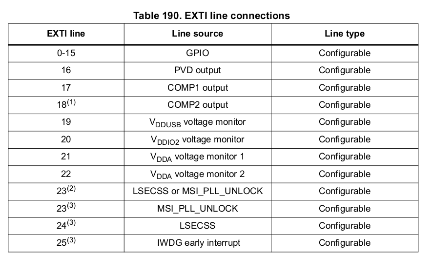
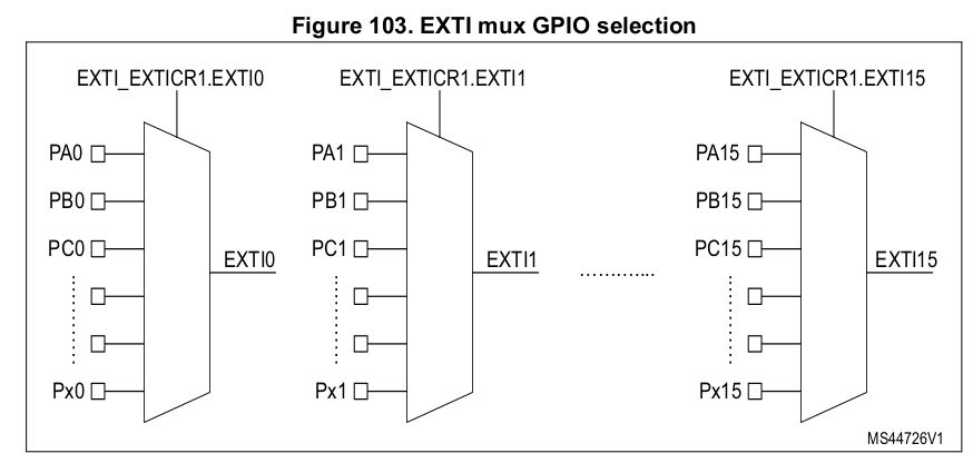
The EXTI peripheral uses something called the EXTI multiplexer (EXTI MUX) to connect external pins to EXTI lines.
- There are 16 EXTI lines (0–15) that can be linked to GPIO pins.
- The connection is configured through registers (EXTI_EXTICR), where you select which port (A, B, C, etc.) connects to each EXTI line.
Not every pin can have its own interrupt line! There are only 16 EXTI lines for all GPIOs, so:
PA0,PB0,PC0,PD0, etc. all share EXTI line 0.PA1,PB1,PC1,PD1, etc. all share EXTI line 1- and so on
So if you use PB0 and PC0 simultaneously, they will share the same interrupt line, and your code must check which pin actually triggered the interrupt.
| Function | Description |
|---|---|
wait_for_high | Suspends the execution until the pin state becomes Level::High. If the pin state is already Level::High, it returns immediately. |
wait_for_low | Suspends the execution until the pin state becomes Level::Low. If the pin state is already Level::Low, it returns immediately. |
wait_for_any_edge | Suspends the execution until the pin state switches. |
wait_for_rising_edge | Suspends the execution until the pin state switches from Level::Low to Level::High |
wait_for_falling_edge | Suspends the execution until the pin state switches Level::High to Level::Low |
Waiting
Embassy provides support for suspending the execution of the software for an amount of time. It uses
the Timer structure from the
embassy_time crate.
// suspend the execution for a period of time
use embassy_time::Timer;

Timer::after_secs(1).await;
If the MCU provides timers, the Embassy framework will use them to suspend the software. This is very efficient.
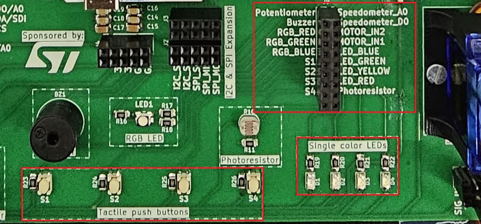
The lab board
This lab makes use of the hardware available on the lab board. The board provides:
- Nucleo U545RE-Q Slot / Board
- 4 buttons
- 5 LEDs
- potentiometer
- buzzer
- photoresistor
- I2C EEPROM
- MPU-6000 accelerometer & Gyro
- BMP 390 Pressure sensor
- SPI LCD Display
- SD Card Reader
- servo connectors
- stepper motor
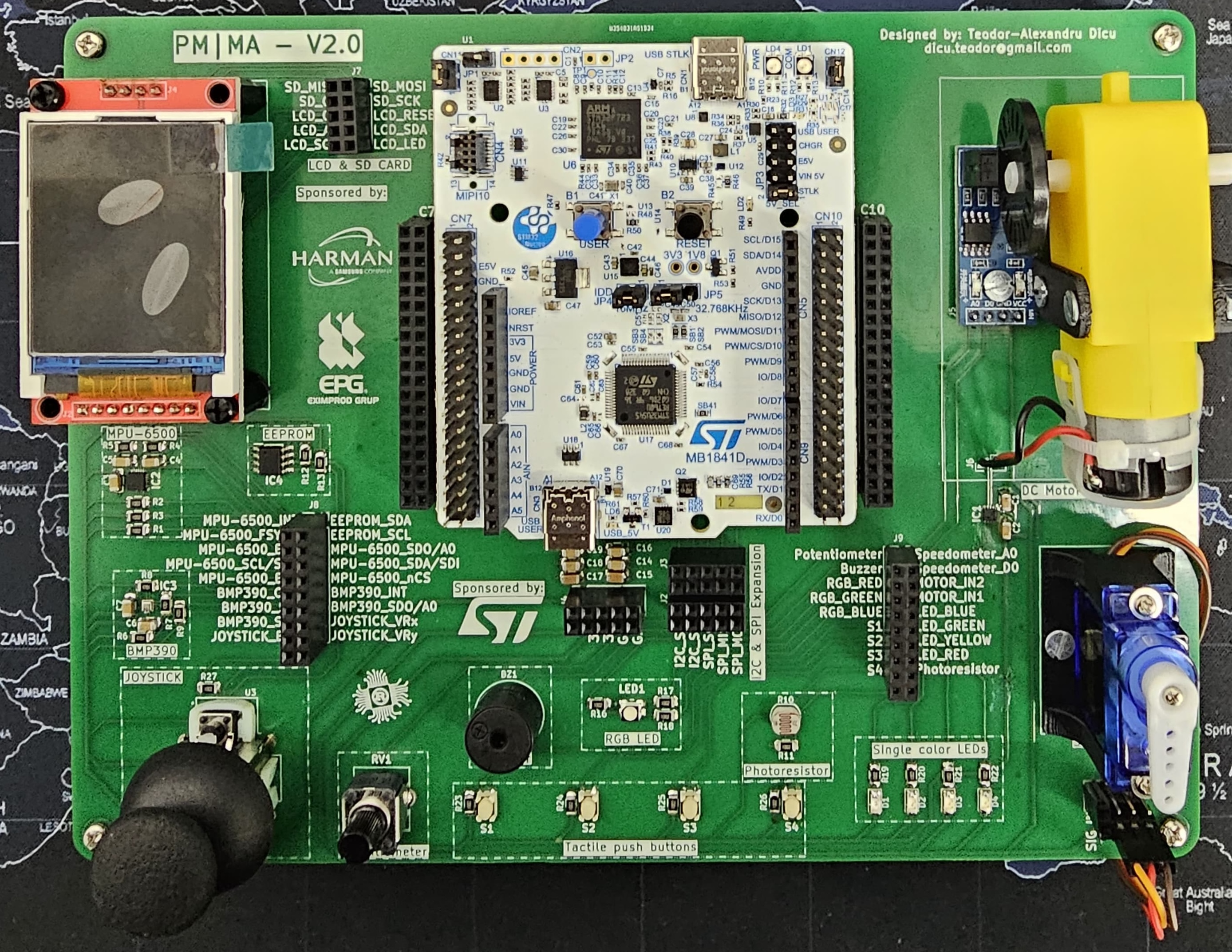
Please make sure you use the USB-C connector(USB STLK) to connect the board to the computer.
Wiring
All the electronic components, sensors and actuators, have the power pins hard wired to the board. This means that all the components receive power from the board and do not have to be powered separately.
The data pins of the components are not wired and have to be connected to the STM32 Nucleo-U545RE-Q/Raspberry Pi Pico using jumper wires.
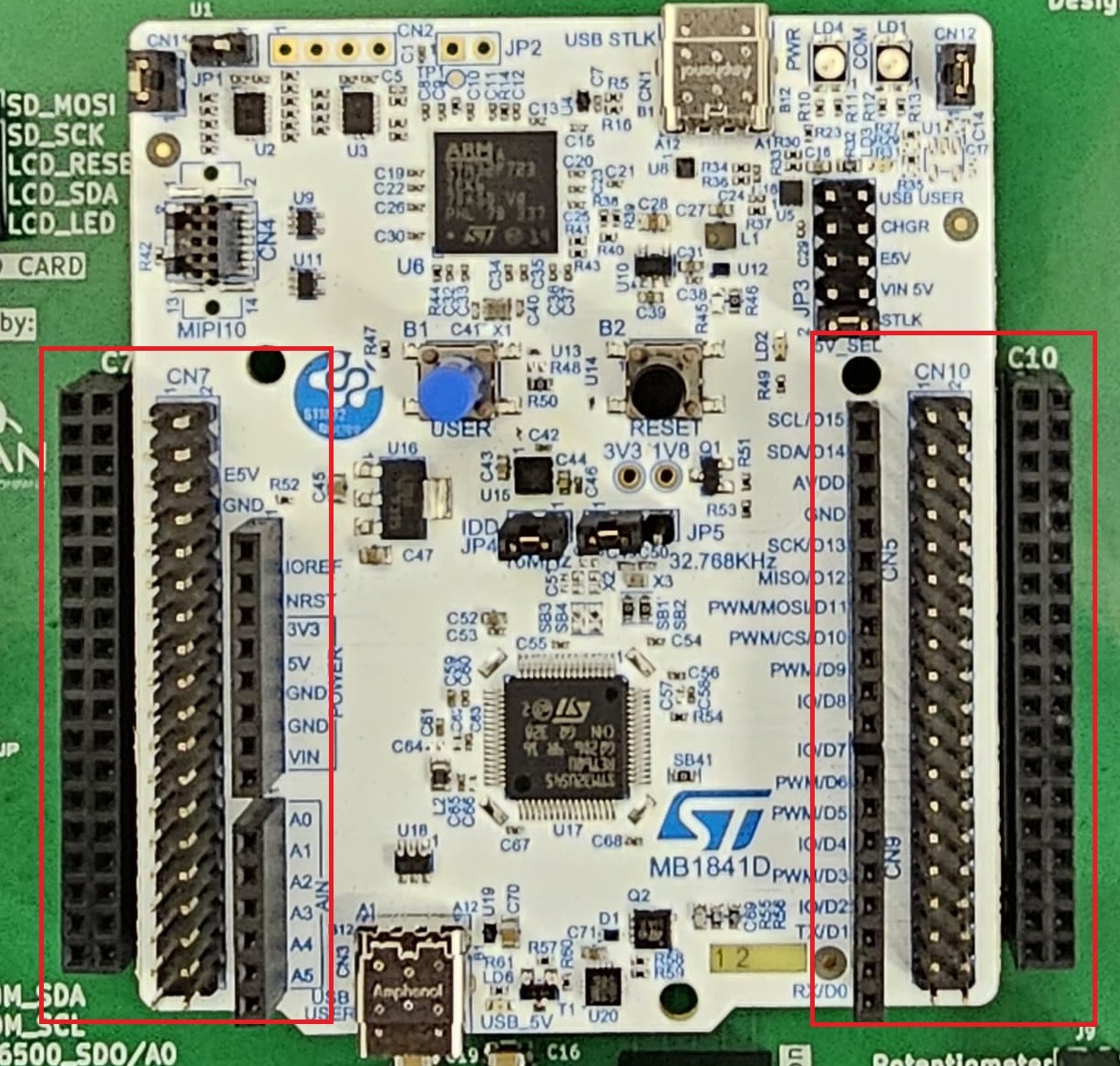
STM32 Nucleo‑U545RE‑Q Pins
Each pin on the STM32 Nucleo‑U545RE‑Q is accessible through Arduino‑compatible headers and ST morpho connectors placed along the sides of the board. The Arduino headers are labeled with familiar names like D0–D15 and A0–A5, while the morpho connectors (CN7, CN8, CN9, CN10) expose the full set of STM32 pins. To identify the exact STM32 signal (e.g., PA5, PB14), you refer to the official pinout diagram in the board’s documentation. These connectors provide flexible access to the GPIO (General‑Purpose Input/Output) pins of the Nucleo board for prototyping and interfacing.
You have to use jumper wires to interface with the STM32 Nucleo‑U545RE‑Q GPIO pins as follows:
- Insert a male jumper wire into one of the pin holes corresponding to the desired GPIO pin.
- Connect the other end of the jumper wire to an external circuit, such as a breadboard, another microcontroller, or a peripheral device. In this case, it will be LEDs or Switches.
- Use the second hole of the same pin as an additional connection point, allowing multiple devices to share the same GPIO.
LEDs and Switches
The board provides four single colored LEDs, red, green, blue and yellow. Each one of them
uses one pin for control. Each LED connector has one single hole on the board,
marked with RED, GREEN, BLUE and YELLOW respectively. These are located in the Connectors
section of the board.
The LEDs are connected so they will light up if the pin is set to Level::Low and turn off if the pin is set to Level::High.
The four switches that the lab board provides are signaled with labels
S1, S2, S3 and S4 in the connectors section.
Switches on the lab board have a pull-up resistor. This means that:
- The values it provides may be counter-intuitive:
| Position | Value |
|---|---|
| Pressed | Level::Low |
| Released | Level::High |
- Pins that connect to switches have to be set up as
Pull::Noneto disable the STM32 Nucleo‑U545RE‑Q's internal pull resistor.
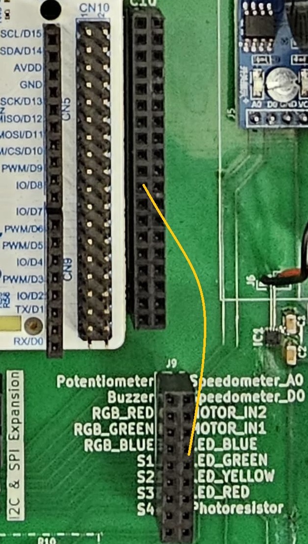
Example
To wire the blue LED to pin PC7 of the STM32 Nucleo‑U545RE‑Q, a jumper cable is required
between holes LED_BLUE and IO/D8.
Exercises
- Write an empty firmware that uses the Embassy Framework and
defmt. (1p) Make sure you follow these steps:
- create a new Rust project using
cargo init; - add the
.cargo/config.tomlfile that instructscargoto cross-compile for thethumbv8m.main-none-eabihfarchitecture, addprobe-rs runas a runner and setdefmtmessages filtering toDEBUG; - add the linker script file called
memory.x; - add the build script file called
build.rs; - add the required Embassy dependencies - take a look at Empty Embassy Firmware - take a look at Empty Firmware;
- use
defmt_rttas a logger, make sure you import it even if you are not using it directlyuse ... as _; - use
panic_probeto provide a panic handler, make sure you import it even if you are not using it directlyuse ... as _; - ask the Rust compiler not to depend on the standard library, not to provide a main function and add the Embassy entry;
- write the code to print the
info!message "Device started".
Please make sure you comment out (using # in from of the line) all the Embassy's crates
that you do not plan to use.
- STM32 Nucleo-U545RE-Q
- Raspberry Pi Pico 1 / 2
Please make sure the embassy_stm32 crate is included in your build either:
- by importing it with
use embassy_stm32 as _; - or by initialising the peripherals
This crate provides the startup and linker sections required for the STM32U545 to boot correctly.
Please make sure the embassy_rp crate is included in your build either:
- by importing it with
use embassy_rp as _; - or by initialising the peripherals
This crate provides the .start_block section that is needed by the RP2350 to boot. Not including
this crate will prevent this section from being added and will prevent the RP2350 to boot.
- Visual Studio Code
- Zed
- Helix
To prevent rust-analyzer from showing an error on the first line and to automatically
format your source when saving, create a .vscode/settings.json file with:
{
  "rust-analyzer.cargo.allTargets": false,
  "[rust]": {
    "editor.defaultFormatter": "rust-lang.rust-analyzer",
    "editor.formatOnSave": true,
    "editor.formatOnSaveMode": "file"
  }
}
To prevent rust-analyzer from showing an error on the first line and to automatically
format your source when saving, create a .zed/settings.json file with:
{
  "lsp": {
    "rust-analyzer": {
      "initialization_options": {
        "cargo": {
          "target": "thumbv8m.main-none-eabihf",
          "allTargets": false
        }
      }
    }
  },
  "inlay_hints": {
    "enabled": true
  }
}
To prevent rust-analyzer from showing an error on the first line and to automatically
format your source when saving, create a .helix/congif.toml file with:
[editor.inline-diagnostics]
cursor-line = "error"

[editor.file-picker]
hidden = false

[editor.lsp]
display-inlay-hints = true
- Write a program using Embassy that set on LOW the LED connected to IO/D8 (PC7). (1p)
Please make sure you to put a loop {} at the end of the main function, otherwise Embassy will reset the
pins at the end of the function and you will not see the LED turn on.
Please make sure the lab professor verifies your circuit before it is powered up.
- Write a program using Embassy that blinks the LED connected to IO/D8 (PC7) every 300ms. (1p)
For the purpose of this lab, please use await as is, think that for
using the Timer, you have to add .await after the after function.
-
Write a program using Embassy that will write the message "The button was pressed" to the console every time button S1 is pressed. Make sure you connect the switch S1 to a STM32 Nucleo-U545RE-Q pin. (1p)
-
Write a Rust program using Embassy that toggles the LED every time button S1 is pressed. The message might be printed many times for one press? Why? (1p)
Read the value of S1 in a loop and print the message if the value is LOW.
- Instead of constantly sampling for the button value, use the wait pin functions to wait for the value to change. Why is the message printed only once? (1p)
Do not forget to write the .await keyword at the end of an async function call.
- Build a traffic light using the
LED_GREEN,LED_YELLOWandLED_REDLEDs. (1p) The flow of the colors is:
- Extend the traffic light to include a flashing blue LED for pedestrians. When the pedestrian button is pressed, the traffic light switches to yellow and waits one second. After that, it switches on the red light and flashes the blue pedestrian light. After 5 seconds, the traffic light switches back to green and stops the blue flashing. (2p)
- Display letters in Morse Code.
- Write a function that takes as an argument a letter and displays it in Morse Code using three LEDs. For a dot light up the middle LED, for a line light up all three. (1p)
- Write a firmware that displays a text in Morse Code. (1p)

Letters in Morse Code are case insensitive. You can use the char::to_ascii_uppercase
or u8::to_ascii_uppercase functions to convert a char or u8 to uppercase.
You can use an array of &strs to store the format of the morse code.
const CODES: [&str; 26] = [
    ".-", // A
    // ...
];
Solutions
The lab's exercises solutions are available in the lab-solutions repository.