Embassy Setup
Here, we will cover the steps needed in order to be able to compile and flash Rust applications for STM32U545 and RP2s, the MCU (Microcontroller Unit) found in our STM32 Nucleo-U545RE-Q and Raspberry Pi Pico boards.
Prerequisites
Rust Toolchain
In order to install the tools needed to compile Rust code, follow the next steps, depending on your operating system.
Linux
Run this command in the terminal:
curl --proto '=https' --tlsv1.2 -sSf https://sh.rustup.rs | sh
This downloads and runs rustup-init.sh, which in turn downloads and runs the correct version of the rustup-init executable for your platform.
Before installing elf2uf2-rs, you need to install pkg-config and libudev. You can install them by running the following command in your terminal:
sudo apt-get install pkg-config libudev-dev
Windows
Download the respective executable:
You may be prompted to install Visual Studio C++ Build tools. If so, follow the instructions from the previous link.
Even if Visual Studio is already on your machine, rustup will not verify if the required components are present. If you experience issues with the rustup installation on Windows, please follow these instructions to manually add the missing components.
The last step is to run rustup --version in terminal. If everything went well, you should see an output similar to this:
rustup 1.26.0 (5af9b9484 2023-04-05)
info: This is the version for the rustup toolchain manager, not the rustc compiler.
info: The currently active `rustc` version is `rustc 1.76.0 (07dca489a 2024-02-04)`
elf2uf2-rs
This tool is needed to be able to program the board over USB. In order to install it, run the following in your terminal:
cargo install elf2uf2-rs
Then, run elf2uf2-rs --help. If it was correctly installed, you should see something similar to this in your terminal:
Usage: elf2uf2-rs [OPTIONS] <INPUT> [OUTPUT]

Arguments:
  <INPUT>   Input file
  [OUTPUT]  Output file

Options:
  -v, --verbose  Verbose
  -d, --deploy   Deploy to any connected pico
  -s, --serial   Connect to serial after deploy
  -h, --help     Print help
probe-rs
This tool is an embedded debugging and target interaction toolkit. It enables its user to program and debug microcontrollers via a debug probe.
cargo install probe-rs-tools --locked
If you are on Linux you will also need to add this udev file in /etc/udev/rules.d. Then, run:
udevadm control --reload # to ensure the new rules are used.

udevadm trigger # to ensure the new rules are applied to already added devices.
VSCode Extension (Optional)
For a better experience, go ahead and install the Debugger for probe-rs extension in the Microsoft Extension Marketplace. This will make debugging the program running on the RP2040 as easy as debugging a Rust program running on your host machine.
Flashing over USB
Compiling
You will need to compile your executable specifically for the target chip. The RP2040 is based on the ARM Cortex‑M0+ architecture, while the STM32U545 and RP2350 are based on the more powerful ARM Cortex‑M33 architecture. In each case, we will need to specify the correct target when compiling. We can do that in multiple ways:
- STM32 Nucleo-U545RE-Q
- Raspberry Pi Pico 2
- Raspberry Pi Pico
- using a
.cargo/config.tomlfile:
[build]
target = "thumbv8m.main-none-eabihf"
- passing it as a parameter to Cargo:
cargo build --release --target thumbv8m.main-none-eabihf
- using a
.cargo/config.tomlfile:
[build]
target = "thumbv8m.main-none-eabihf"
- passing it as a parameter to Cargo:
cargo build --release --target thumbv8m.main-none-eabihf
- using a
.cargo/config.tomlfile:
[build]
target = "thumbv6m-none-eabi"
- passing it as a parameter to Cargo:
cargo build --release --target thumbv6m-none-eabi
Flashing
- STM32 Nucleo-U545RE-Q
- Raspberry Pi Pico
For the STM32U545, flashing is typically done through its built‑in DFU (Device Firmware Upgrade) mode or via a debug probe such as ST‑LINK. To enter DFU mode, you usually hold the BOOT0 pin high while resetting the device, which makes it appear as a USB device to your PC. Once in this mode, you can flash new firmware without repeatedly plugging and unplugging the USB cable. Many development boards also include a reset button to simplify this process.
To flash a program to the Raspberry Pi Pico via USB, it needs to be in USB mass storage device mode. To put it in this mode, you need to hold the BOOTSEL button down while connecting it to your PC. Frequently connecting and disconnecting the USB cable can damage the port, so we conveniently attached a reset button on the breadboard included on the Pico Explorer Base. Now, to make it reflashable again, just press the two buttons simultaneously.
After connecting the board to your PC and compiling the program, locate the binary in the target/thumbv6m-none-eabi/release/ folder then, run:
elf2uf2-rs -d -s /path/to/your/binary
-dto automatically deploy to a mounted pico-sto open the pico as a serial device after deploy and print serial output
On Windows, you may need to run this command in a terminal that has Admin Privileges.
Debugging using Raspberry Pi Debug Probe
In order to be able to debug the program running on the board, we will need to connect the Raspberry Pi Debug Probe to our Raspberry Pi Pico W. Below is a picture of the provided debug kit:
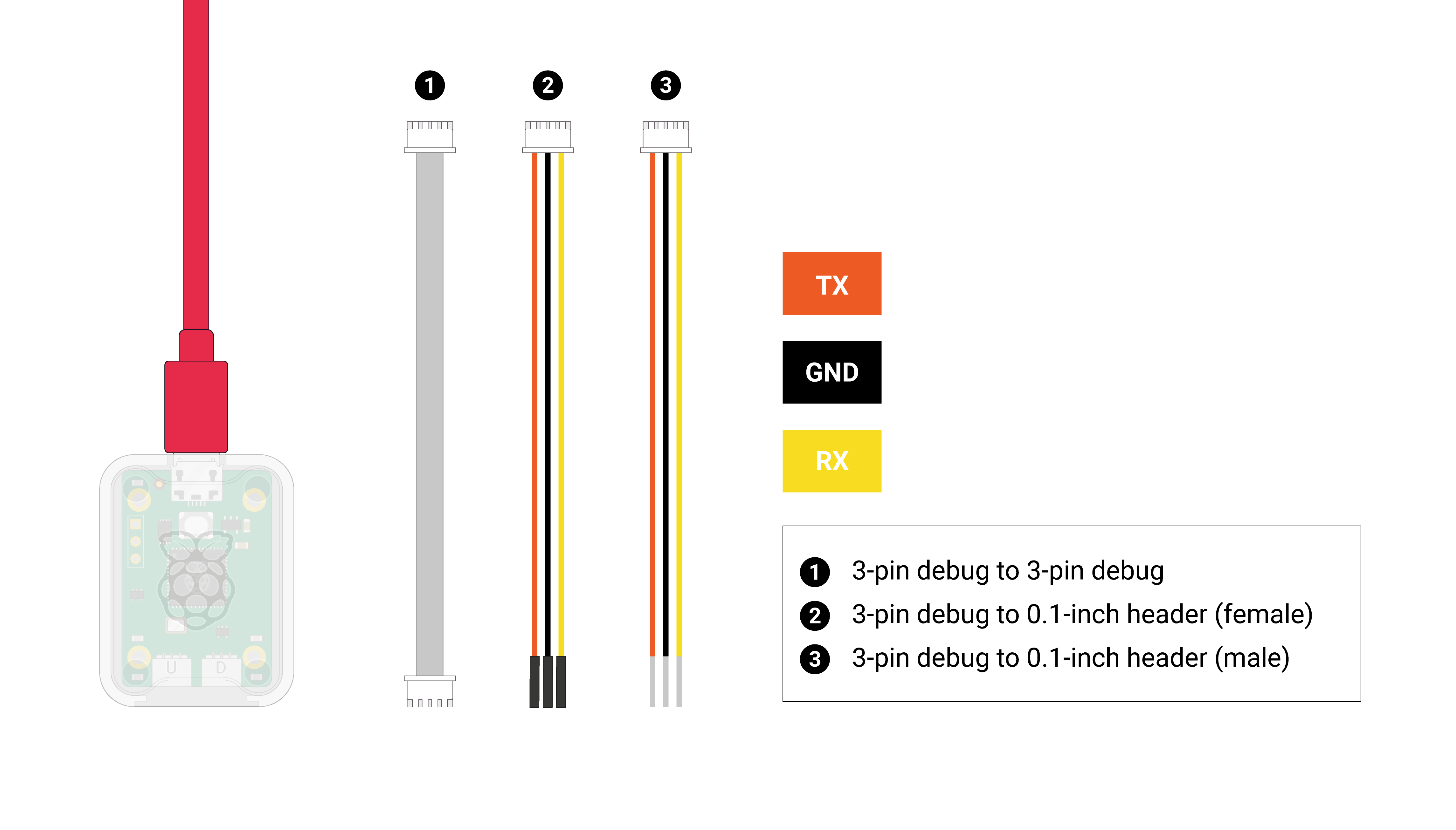
To connect them, we will use the 3-pin debug to 0.1-inch header (female) cable. First, carefully insert the 3-pin debug head in the right side connector. Then you will also need to connect it to the Raspberry Pi Pico W. You can find the pinout below, take a closer look at the bottom of the image:

The connections must be:
| Wire | Raspberry Pi Pico W |
|---|---|
| TX (Orange) | SWCLK |
| GND (Black) | GND |
| RX (Yellow) | SWDIO |
Do not forget to connect both the Debug Probe and Pico to your PC.
Now, you can either debug using the command line by running:
- STM32 Nucleo-U545RE-Q
- Raspberry Pi Pico 2
- Raspberry Pi Pico
probe-rs run --chip STM32U545RETxQ path/to/your/binary
probe-rs run --chip RP2350 path/to/your/binary
probe-rs run --chip RP2040 path/to/your/binary
or you can use the Run and Debug view in Visual Studio Code. You will need to modify the programBinary path in the .vscode/launch.json config file to point to your binary file.
Building your first Embassy project
In this section, we will briefly go over the steps you need to take in order to get your first project using Rust and Embassy going.
Creating your crate
The first step is to create your cargo package by running the following command in your terminal:
cargo new --vcs none embassy
--vcs nonebecause at the moment we do not want to use any code versioning (they are useful, but this is not the purpose of this tutorial)
Crate settings
Because we are running in an embedded environment, our code needs to be "tailored" specifically for the microcontroller we intend to use. In our case, it is the STM32U545 and RP2s, but these general steps apply for any chip, produced by any manufacturer.
No standard library
Due to the size constraints imposed on us (in our case, 2MB of flash memory), the standard library has to go. We specify that by adding the #![no_std] attribute to the beginning of our src/mains.rs file.
No main function
Because we are using the Embassy framework, we want to let it take care of the entry point of our program (because it has to do some complex operations, like allocating the task-arena and executor structures). For the moment, all we will need to do is add the #![no_main] attribute to src/main.rs.
Toolchain setting
Our chip can be one of several Cortex‑M families, and we need to specify the correct target triple when compiling. The RP2040 is a Cortex‑M0+ that uses the ThumbV6‑M architecture, while the Raspberry Pi Pico 2 and the STM32U545 are both Cortex‑M33 devices that use the ThumbV8‑M.main architecture. We will do that using a rust-toolchain.toml file, as it allows us to also set the toolchain release channel we will use, and the components we require.
An example of such file is this:
rust-toolchain.toml
# This file is used to specify the version of the Rust toolchain that
# should be used for your project.

[toolchain]
# The release to be used.
channel = "1.90"
# The targets for compilation that need to be added. This is used for
# cross-compilation, as the executables we are producing need to be
# run on our boards.
targets = ["thumbv6m-none-eabi", "thumbv8m.main-none-eabihf"]
# The additional componets to be installed along the Rust toolchain
components = ["rust-src", "rustfmt", "llvm-tools", "clippy"]
We can use the same rust-toolchain.toml file for both the RP2350 and the STM32U545, we just need to make sure to add both target triples. The RP2040 is a Cortex-M0+ that uses the thumbv6m-none-eabi target while the RP2350 and STM32U545 are both Cortex‑M33 devices, so they use the thumbv8m.main-none-eabi target.
- STM32 Nucleo-U545RE-Q/Raspberry Pi Pico 2
- Raspberry Pi Pico
Please make sure that you install the Rust ARMv8-M target (thumbv8m.main-none-eabihf).
rustup target add thumbv8m.main-none-eabihf
You can skip this step when the target is defined in rust-toolchain.toml.
Please make sure that you install the Rust ARMv6-M target (thumbv6m-none-eabi).
rustup target add thumbv6m-none-eabi
You can skip this step when the target is defined in rust-toolchain.toml.
Memory layout
We also need to take care of the memory layout of our program when writing code for a microcontroller. These can be found in the datasheet of all the microcontrollers. Below, you can find the memory layout for the STM32U545 and RP2s:
memory.x
- STM32 Nucleo-U545RE-Q
- Raspberry Pi Pico 2
- Raspberry Pi Pico
MEMORY
{
  /* On-chip Flash memory */
  FLASH (rx) : ORIGIN = 0x08000000, LENGTH = 512K

  /* On-chip SRAM (SRAM1+SRAM2+SRAM3 combined) */
  RAM (rwx)  : ORIGIN = 0x20000000, LENGTH = 256K
}
You don’t need to provide a memory.x file when using Embassy, because the embassy-stm32 crate has a feature called memory-x
that already supplies the required linker script.
MEMORY {
    /*
     * The RP2350 has either external or internal flash.
     *
     * 2 MiB is a safe default here, although a Pico 2 has 4 MiB.
     */
    FLASH : ORIGIN = 0x10000000, LENGTH = 2048K
    /*
     * RAM consists of 8 banks, SRAM0-SRAM7, with a striped mapping.
     * This is usually good for performance, as it distributes load on
     * those banks evenly.
     */
    RAM : ORIGIN = 0x20000000, LENGTH = 512K
    /*
     * RAM banks 8 and 9 use a direct mapping. They can be used to have
     * memory areas dedicated for some specific job, improving predictability
     * of access times.
     * Example: Separate stacks for core0 and core1.
     */
    SRAM4 : ORIGIN = 0x20080000, LENGTH = 4K
    SRAM5 : ORIGIN = 0x20081000, LENGTH = 4K
}

SECTIONS {
    /* ### Boot ROM info
     *
     * Goes after .vector_table, to keep it in the first 4K of flash
     * where the Boot ROM (and picotool) can find it
     */
    .start_block : ALIGN(4)
    {
        __start_block_addr = .;
        KEEP(*(.start_block));
        KEEP(*(.boot_info));
    } > FLASH

} INSERT AFTER .vector_table;

/* move .text to start /after/ the boot info */
_stext = ADDR(.start_block) + SIZEOF(.start_block);

SECTIONS {
    /* ### Picotool 'Binary Info' Entries
     *
     * Picotool looks through this block (as we have pointers to it in our
     * header) to find interesting information.
     */
    .bi_entries : ALIGN(4)
    {
        /* We put this in the header */
        __bi_entries_start = .;
        /* Here are the entries */
        KEEP(*(.bi_entries));
        /* Keep this block a nice round size */
        . = ALIGN(4);
        /* We put this in the header */
        __bi_entries_end = .;
    } > FLASH
} INSERT AFTER .text;

SECTIONS {
    /* ### Boot ROM extra info
     *
     * Goes after everything in our program, so it can contain a signature.
     */
    .end_block : ALIGN(4)
    {
        __end_block_addr = .;
        KEEP(*(.end_block));
    } > FLASH

} INSERT AFTER .uninit;

PROVIDE(start_to_end = __end_block_addr - __start_block_addr);
PROVIDE(end_to_start = __start_block_addr - __end_block_addr);
You don’t need to provide a memory.x file when using Embassy,
because the embassy-rp crate has a feature called memory-x
that already supplies the required linker script.
MEMORY {
    BOOT2 : ORIGIN = 0x10000000, LENGTH = 0x100
    /*
     * Here we assume you have 2048 KiB of Flash. This is what the Pi Pico
     * has, but your board may have more or less Flash and you should adjust
     * this value to suit.
     */
    FLASH : ORIGIN = 0x10000100, LENGTH = 2048K - 0x100
    /*
     * RAM consists of 4 banks, SRAM0-SRAM3, with a striped mapping.
     * This is usually good for performance, as it distributes load on
     * those banks evenly.
     */
    RAM : ORIGIN = 0x20000000, LENGTH = 256K
    /*
     * RAM banks 4 and 5 use a direct mapping. They can be used to have
     * memory areas dedicated for some specific job, improving predictability
     * of access times.
     * Example: Separate stacks for core0 and core1.
     */
    SRAM4 : ORIGIN = 0x20040000, LENGTH = 4k
    SRAM5 : ORIGIN = 0x20041000, LENGTH = 4k

    /* SRAM banks 0-3 can also be accessed directly. However, those ranges
       alias with the RAM mapping, above. So don't use them at the same time!
    SRAM0 : ORIGIN = 0x21000000, LENGTH = 64k
    SRAM1 : ORIGIN = 0x21010000, LENGTH = 64k
    SRAM2 : ORIGIN = 0x21020000, LENGTH = 64k
    SRAM3 : ORIGIN = 0x21030000, LENGTH = 64k
    */
}

EXTERN(BOOT2_FIRMWARE)

SECTIONS {
    /* ### Boot loader
     *
     * An executable block of code which sets up the QSPI interface for
     * 'Execute-In-Place' (or XIP) mode. Also sends chip-specific commands to
     * the external flash chip.
     *
     * Must go at the start of external flash, where the Boot ROM expects it.
     */
    .boot2 ORIGIN(BOOT2) :
    {
        KEEP(*(.boot2));
    } > BOOT2
} INSERT BEFORE .text;

SECTIONS {
    /* ### Boot ROM info
     *
     * Goes after .vector_table, to keep it in the first 512 bytes of flash,
     * where picotool can find it
     */
    .boot_info : ALIGN(4)
    {
        KEEP(*(.boot_info));
    } > FLASH

} INSERT AFTER .vector_table;

/* move .text to start /after/ the boot info */
_stext = ADDR(.boot_info) + SIZEOF(.boot_info);

SECTIONS {
    /* ### Picotool 'Binary Info' Entries
     *
     * Picotool looks through this block (as we have pointers to it in our
     * header) to find interesting information.
     */
    .bi_entries : ALIGN(4)
    {
        /* We put this in the header */
        __bi_entries_start = .;
        /* Here are the entries */
        KEEP(*(.bi_entries));
        /* Keep this block a nice round size */
        . = ALIGN(4);
        /* We put this in the header */
        __bi_entries_end = .;
    } > FLASH
} INSERT AFTER .text;
You don’t need to provide a memory.x file when using Embassy,
because the embassy-rp crate has a feature called memory-x
that already supplies the required linker script.
To use the memory.x layout file, we will also need to use a build script. Rust facilitates that through the build.rs file. Below you will find an explained build script you can use.
build.rs
//! This build script copies the `memory.x` file from the crate root into
//! a directory where the linker can always find it at build time.
//! For many projects this is optional, as the linker always searches the
//! project root directory -- wherever `Cargo.toml` is. However, if you
//! are using a workspace or have a more complicated build setup, this
//! build script becomes required. Additionally, by requesting that
//! Cargo re-run the build script whenever `memory.x` is changed,
//! updating `memory.x` ensures a rebuild of the application with the
//! new memory settings.

use std::env;
use std::fs::File;
use std::io::Write;
use std::path::PathBuf;

fn main() {
    // Put `memory.x` in our output directory and ensure it's
    // on the linker search path.
    let out = &PathBuf::from(env::var_os("OUT_DIR").unwrap());
    File::create(out.join("memory.x"))
        .unwrap()
        .write_all(include_bytes!("./memory.x"))
        .unwrap();
    println!("cargo:rustc-link-search={}", out.display());
    println!("cargo:rerun-if-changed={{layout}}");

    // `--nmagic` is required if memory section addresses are not aligned to 0x10000,
    // for example the FLASH and RAM sections in your `memory.x`.
    println!("cargo:rustc-link-arg=--nmagic");

    // The `link.x` linker script provided by `cortex_m_rt` (minimal runtime for
    // Cortex-M microcontrollers used by embassy) will include our `memory.x` memory layout.
    println!("cargo:rustc-link-arg=-Tlink.x");

    // The `link-rp.x` linker script provided by `embassy_rp` that defines the
    // BOOT2 section.
    println!("cargo:rustc-link-arg-bins=-Tlink-rp.x");

    // The `defmt.x` linker script provided by `defmt`.
    println!("cargo:rustc-link-arg-bins=-Tdefmt.x");
}
If you are using the memory.x provided by embassy comment this part:
    let out = &PathBuf::from(env::var_os("OUT_DIR").unwrap());
    File::create(out.join("memory.x"))
        .unwrap()
        .write_all(include_bytes!("./memory.x"))
        .unwrap();
    println!("cargo:rustc-link-search={}", out.display());
    println!("cargo:rerun-if-changed={{layout}}");
Adding the Dependencies
At this step, we must add the dependencies we will use for our project. Below you will find the basics you will need for a minimal application, including an usb_logger to "enable" debugging over serial.
embassy-executor
This is an async/await executor designed for embedded. To add it as a dependency to your project, run:
cargo add embassy-executor --features arch-cortex-m,executor-thread,executor-interrupt,integrated-timers,task-arena-size-32768
arch-cortex-m- feature to specify we are running on the cortex M architectureexecutor-thread- enable the thread-mode executor (using WFE/SEV in Cortex-M, WFI in other embedded archs)executor-interrupt- enable the interrupt-mode executor (available in Cortex-M only)integrated-timers- use the executor-integrated embassy-time timer queue.task-arena-size-X- sets the task arena size
We will also need to add the cortex-m and cortex-m-rt crates as dependencies, as the #[executor::main] attribute depends on the minimal startup code for the Cortex M microcontrollers found in these crates. To do that, run:
cargo add cortex-m
cargo add cortex-m-rt
embassy-time
This crate enables timekeeping, timeouts and delays. Add it by running:
cargo add embassy-time
embassy-stm32
This crate is a Hardware Abstraction Layer for the STM32U545. You can add it to your project like so:
cargo add embassy-stm32 --features time-driver-any
time-driver-any- enable the timer for use withembassy-time.
embassy-usb-logger
USB implementation of the log crate. It allows the usage of info! macro and some more. To add it, run the following command:
cargo add log
cargo add embassy-usb-logger
panic-probe
This crate adds a panic handler for the microchip that prints panic messages over JTAG, and in order to add it, run:
cargo add panic-probe
The code
Here you can find a minimally explained code that prints "Hello World!" over the serial interface:
main.rs
- STM32 Nucleo-U545RE-Q
- Raspberry Pi Pico 2
#![no_std]
#![no_main]

use defmt::info;
use embassy_executor::Spawner;
use embassy_stm32::{self as _, Config};

use defmt_rtt as _;
use embassy_time::Timer;
use panic_probe as _;

#[embassy_executor::main]
async fn main(_spawner: Spawner) {
    let config = Config::default();
    let _peripherals = embassy_stm32::init(config);
    loop {
        info!("Hello, World!");
        Timer::after_secs(1).await;
    }
}
#![no_std]
#![no_main]

use embassy_executor::Spawner;
use embassy_rp::bind_interrupts;
use embassy_rp::peripherals::USB;
use embassy_rp::usb::{Driver, InterruptHandler as UsbInterruptHandler};
use embassy_time::Timer;
use log::info;
use panic_probe as _;

// Bind interrupts to their handlers.
bind_interrupts!(struct Irqs {
    USBCTRL_IRQ => UsbInterruptHandler<USB>;
});

// Async task for USB logging.
#[embassy_executor::task]
async fn logger_task(driver: Driver<'static, USB>) {
    embassy_usb_logger::run!(1024, log::LevelFilter::Info, driver);
}

#[embassy_executor::main]
async fn main(spawner: Spawner) {
    // Initialize peripherals and USB driver.
    let rp_peripherals = embassy_rp::init(Default::default());
    let usb_driver = Driver::new(rp_peripherals.USB, Irqs);

    // Spawn the logger task
    spawner.spawn(logger_task(usb_driver)).unwrap();

    Timer::after_millis(1000).await;
    info!("Hello, world!");

    loop {
        Timer::after_millis(10).await;
    }
}